A 48V servo motor can be a suitable option for battery-powered automated guided vehicles (AGVs) and autonomous mobile robots (AMRs). However, voltage and rated power alone do not establish whether a motor can move the required payload, climb a ramp, or operate continuously inside a compact chassis.
Start with the vehicle's wheel torque and speed requirements, then match the motor, gearbox, drive, battery, and braking system. This approach helps buyers compare complete drive solutions rather than choosing a motor by wattage alone.
Table of Contents
Toggle
1. Match the 48V Servo Motor to the Battery System
Check the full operating voltage range
A nominal 48V battery does not maintain exactly 48V throughout operation. Its voltage changes with chemistry, state of charge, temperature, current demand, and battery-management settings.
Provide the drive supplier with the battery's maximum charged voltage, minimum operating voltage, expected voltage sag, and transient conditions. Confirm that the drive remains within its limits and that the motor can deliver the required torque and speed at the lowest expected bus voltage.
A low battery voltage can reduce the available high-speed operating range. Conversely, charging conditions and regenerative braking can raise the DC bus voltage. Both ends of the range matter.
Separate battery current from motor phase current
For the same DC input power, increasing bus voltage reduces battery-side current. For example, an ideal 1,000W electrical load draws approximately 41.7A at 24V or 20.8A at 48V.
These figures are not motor phase-current ratings. Phase current depends on torque demand, motor winding, drive operation, and the current convention used in the specification. Do not use a battery-current calculation to select the drive's phase-current capacity.
Likewise, 48V operation does not automatically justify a smaller cable. Cable sizing must consider continuous and peak current, voltage drop, installation temperature, bundling, protection, and connector ratings.
2. Calculate Wheel Torque and Motor Speed
Build the traction requirement from the vehicle duty
Use total loaded vehicle mass rather than payload alone. A preliminary straight-line traction calculation can include:
F = m × a + Crr × m × g × cos(θ) + m × g × sin(θ)
Here, F is required tractive force, m is total mass, a is acceleration, Crr is the rolling-resistance coefficient, g is gravitational acceleration, and θ is the ramp angle.
This simplified calculation does not include every loss. Turning resistance, caster behavior, wheel deformation, rotating inertia, floor joints, and obstacles may require additional analysis or testing.
For equally loaded drive wheels, a preliminary motor-shaft torque estimate is:
Tmotor = F × r ÷ (N × i × η)
Here, r is wheel radius, N is the number of driven wheels sharing the force, i is the reduction ratio defined as motor speed divided by wheel speed, and η is transmission efficiency.
Check speed and torque together
Wheel and motor speeds can be estimated from vehicle speed:
nwheel = 60 × v ÷ (2 × π × r)
nmotor = nwheel × i
In these equations, v is vehicle speed in m/s, r is wheel radius in metres, and rotational speed is in r/min.
Illustrative input
Value
Total loaded mass
300 kg
Acceleration
0.3 m/s²
Rolling-resistance coefficient
0.02, assumed for illustration
Ramp angle
3°
Wheel radius
0.1 m
Driven wheels
2, assumed equal force sharing
Reduction ratio and efficiency
20:1 and 0.9
Using g = 9.81 m/s² gives approximately 303N of tractive force and 0.84N·m per motor before additional allowances and rotating-inertia effects. At 1m/s vehicle speed, wheel speed is approximately 95.5r/min and motor speed is approximately 1,910r/min.
This is a calculation example, not a product recommendation. Verify traction limits, load distribution, gearbox capacity, and the complete torque-speed duty before selecting a motor.
3. Compare Continuous Torque, Peak Torque, and Thermal Duty
Do not size from peak torque alone
Continuous torque applies under specified thermal conditions. Peak torque is available only within the motor and drive's current, duration, and temperature limits. Repeated starts or sustained ramp travel can overheat a motor even if each event remains below its published peak torque.
Review the complete operating cycle, including acceleration, cruising, turning, braking, waiting, and slope holding. RMS torque can support preliminary thermal sizing, but it must be checked alongside speed-dependent losses, cooling conditions, and the manufacturer's torque-speed envelope.
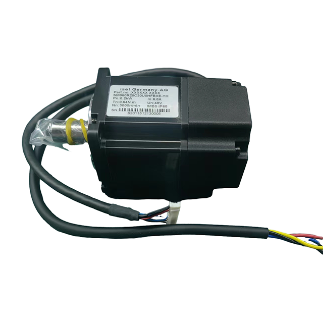
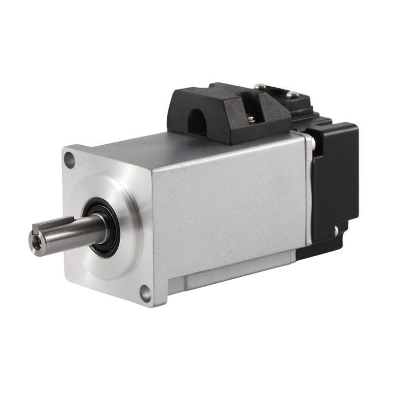
Tiger Motion's 60-frame 200W 48V servo motor lists 0.64N·m rated torque, 1.92N·m instantaneous maximum torque, and 3,000r/min rated speed. The duration and operating conditions permitted for peak torque should be confirmed separately.
In the calculation example above, 0.84N·m exceeds this model's listed rated torque. A peak rating above that requirement would not, by itself, establish suitability for continuous climbing.
Compare the proposed motor's rated torque, peak limits, and speed against the complete vehicle duty.
Validate the installed thermal conditions
Ratings obtained with a specified mounting plate and ambient temperature may not transfer directly to an enclosed mobile chassis. Confirm the mounting heat path, surrounding temperature, ventilation, and any required derating.
An insulation class is not a permitted housing temperature or a guarantee of service life. Similarly, an ingress-protection rating must be read with its stated exclusions, including shaft and connector arrangements.
For smaller mechanisms, the 40-frame 100W 48V servo motor provides another product reference. Its suitability still depends on the calculated load and integration conditions.
4. Match the Drive, Feedback, Gearbox, and Braking System
Confirm electrical and communication compatibility
The drive must support the motor's winding characteristics, continuous and peak phase currents, feedback interface, and required control modes. Check whether current values are RMS or peak before comparing specifications.
EtherCAT, CANopen, or another communication protocol is normally a drive or controller feature, not a property established by the motor's voltage rating. Confirm the exact hardware, firmware, device profile, and supported functions.
Encoder resolution affects shaft feedback, but it does not establish vehicle positioning accuracy by itself. Wheel slip, gearbox backlash, wheel diameter variation, navigation sensors, and control tuning also matter. An absolute motor encoder does not automatically restore the robot's global position after power loss.
Review the complete mechanical load path
For a geared servo system, verify output torque, reduction ratio, efficiency, backlash, bearing loads, and service requirements. Avoid applying wheel radial loads directly to the motor shaft unless the arrangement is approved.
A direct-drive wheel motor can remove gearbox backlash, but it must provide the required wheel torque at low speed. Neither geared nor direct-drive construction is universally more efficient; compare the actual duty and efficiency maps.
Safe Torque Off (STO), where provided by a suitable drive, prevents torque-producing operation. It does not actively brake the vehicle, provide electrical isolation, or hold the robot on a slope. The vehicle may coast or move under an external load.
The Beckhoff STO operating instructions explain this distinction. Safety functions, stopping performance, and brake control must be defined and validated at vehicle level; a component rating does not certify the complete AGV or AMR.
Also review regenerative energy. During deceleration or downhill travel, energy can return to the DC bus. Confirm battery charge acceptance, BMS behavior, drive overvoltage limits, and any required energy-management hardware. A holding brake should not be treated as a repeated service brake without an appropriate rating.
5. Prepare a Complete AGV or AMR Motor Sourcing Brief
Provide the operating data that determines selection
Total vehicle mass, payload range, and driven-wheel arrangement.
Wheel diameter, maximum speed, acceleration, and stopping requirements.
Maximum ramp angle, floor conditions, turning behavior, and traction assumptions.
Battery chemistry, operating voltage range, current limits, and regenerative charging limits.
Operating cycle, ambient temperature, enclosure, and mounting heat path.
Required gearbox ratio, shaft interface, bearing loads, and available space.
Drive, encoder, communication, braking, and vehicle safety requirements.
Prototype quantity, annual demand, required documents, and acceptance tests.
Approve the system through representative testing
Bench tests should be followed by loaded vehicle trials. Include low-battery acceleration, sustained ramp operation, turning, thermal stabilization, regenerative braking, and fault recovery under an agreed test plan.
To discuss a proposed drive, send Tiger Motion your AGV or AMR operating requirements, including the load cycle, wheel size, battery range, torque-speed targets, and mechanical drawing. Request confirmation of the suitable motor configuration, available feedback and brake options, and matching-drive requirements before ordering.
FAQ
Q: Is a 48V servo motor always more efficient than a 24V motor?
A: No. Higher voltage reduces battery-side current for the same electrical power, but total efficiency depends on the motor winding, drive, gearbox, operating point, and losses throughout the system.
Q: Can a 48V servo motor connect directly to a battery?
A: A servo system requires a compatible drive to control motor phase currents and process feedback. Confirm the motor topology and wiring instructions; the DC voltage designation does not imply direct battery connection.
Q: Can a standard servo motor drive an AGV wheel without a gearbox?
A: Only if its low-speed torque, thermal performance, shaft loading, and control behavior meet the application. A conventional high-speed servo should not be assumed suitable for direct wheel drive.
Q: Does an absolute encoder eliminate AMR localization after a restart?
A: No. It can retain or recover shaft-position information according to its design, but vehicle localization also depends on wheel motion, slip, navigation sensors, and the robot controller.
Q: Does a 48V system automatically qualify as SELV?
A: No. Nominal voltage alone does not establish SELV classification. The applicable standard, maximum voltage, protective separation, installation, and fault conditions must be assessed for the complete circuit.