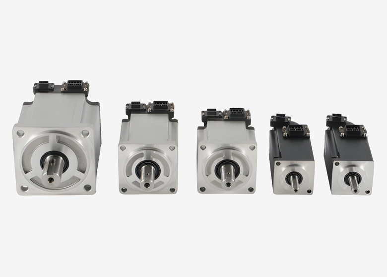
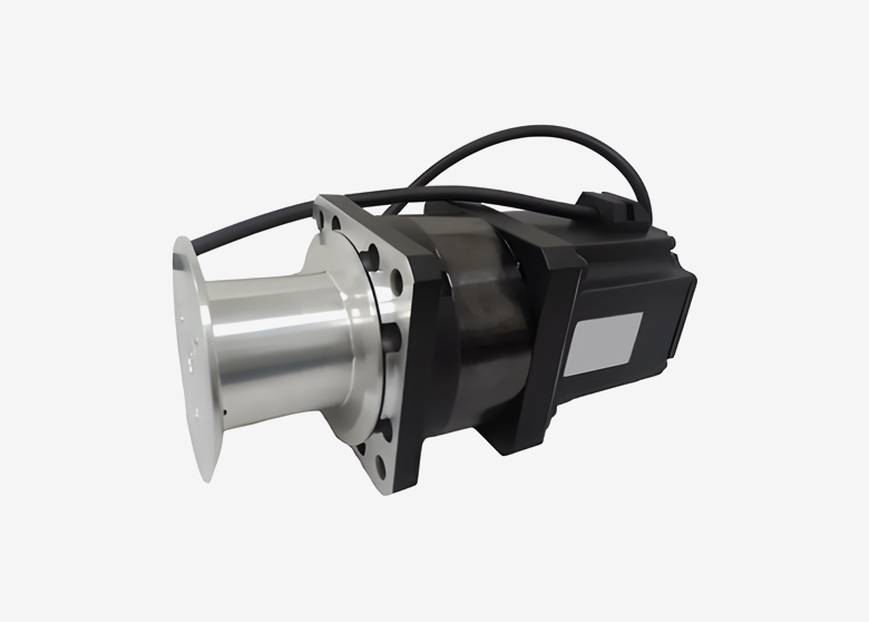
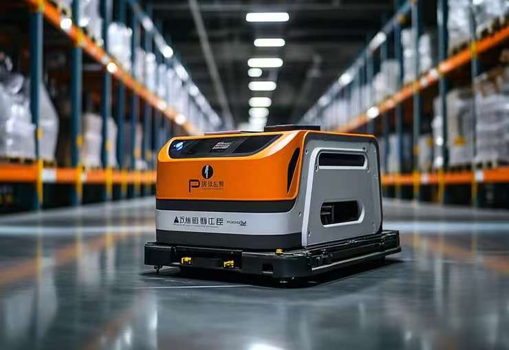
Servo motors for warehouse transfer and AS/RS systems can support repeated positioning, controlled acceleration, and coordinated movement. Applications include shuttle travel, stacker-crane axes, telescopic extractors, and transfer mechanisms.
However, these axes do not share one motor specification. A horizontal shuttle must overcome travel resistance and accelerate its moving mass. A hoist must also manage gravity, suspended loads, and lowering energy.
The right selection starts with the mechanism and operating cycle. Motor power, encoder resolution, or network speed alone cannot establish retrieval throughput or positioning performance.
Table of Contents
Toggle
Where Servo Motors Fit in Warehouse Automation
An automated storage and retrieval system combines mechanical equipment, sensing, controls, and warehouse software. The drive system executes movement, while higher-level software manages tasks and inventory flow.
Throughput depends on the complete operation, including travel, settling, load handling, queuing, and transfer availability.
Compare the main axis duties
Axis or mechanism
Main duty
Important selection inputs
Horizontal shuttle
Move totes or carriers between positions
Moving mass, wheel or pulley geometry, resistance, acceleration, and traction
Stacker-crane travel
Position the crane along an aisle
Total moving mass, travel distance, transmission, and mast response
Vertical hoist
Raise and lower a carriage and payload
Gravity load, counterbalance, acceleration, holding, and regenerated energy
Telescopic extractor
Insert or retrieve a load
Extension geometry, friction, changing load distribution, and alignment
Transfer conveyor
Exchange loads with adjacent equipment
Belt or roller resistance, index distance, product restraint, and timing
Mobile warehouse robot
Travel and dock at transfer points
Battery range, wheel loading, traction, steering, and localization
Not every warehouse axis requires servo control. Continuous conveyors may use geared motors with suitable variable-speed drives. Some modest positioning duties may also be served by stepper or other actuator systems.
Compare the required motion performance with the capabilities of the complete drive arrangement.
Understand motor terminology
“Servo” describes feedback-controlled operation. “BLDC” describes a brushless motor construction and commutation terminology. A brushless motor can form part of a servo system when paired with appropriate feedback, drive electronics, and controls.
Likewise, induction motors can operate with feedback-controlled drives. They should not be described as incapable of positioning simply because basic conveyor installations often use speed control.
Tiger Motion’s standard servo motor range provides options to review against an axis specification. Confirm the selected motor’s ratings and compatible drive rather than choosing by technology label alone.
How to Size Servo Motors for Warehouse Transfer
Define the complete movement cycle
Document the moving mass, payload range, travel distance, speed, acceleration, dwell, and cycle frequency for each axis.
Include the carriage, forks, cables, chains, and other moving components where relevant. For lifting mechanisms, account for counterweights or counterbalances and the forces in both directions.
The most demanding condition may not be the heaviest payload. An empty counterweighted carriage can produce a different peak demand, while an extended extractor may change load distribution and mechanical stiffness.
Calculate torque at the motor shaft
A useful rotary-axis relationship is:
Required motor torque = acceleration torque + resisting torque + gravity torque, where applicable
Acceleration torque depends on total inertia referred to the motor shaft and angular acceleration. Resistance includes the relevant friction and process forces, with transmission efficiency treated appropriately.
Check:
Peak torque during acceleration, deceleration, and load transfer.
Required torque throughout the speed range.
RMS torque over the representative cycle.
Permitted overload duration.
Drive current and supply capability.
Holding periods and low-speed operation.
Thermal limits under actual installation conditions.
Do not use rated power as a substitute for torque-speed analysis. The drive, supply voltage, winding, and operating conditions affect the usable performance envelope.
Evaluate reflected inertia and transmission limits
Load inertia must be reflected through the actual transmission. For a rotary load behind an ideal reduction gearbox, reflected inertia decreases with the square of the reduction ratio.
There is no universal 5:1 or 10:1 requirement that determines whether every warehouse axis will be stable. Mechanical stiffness, compliance, control bandwidth, and the required settling time also matter.
A gearbox can increase output torque and adjust motor speed, but it adds losses, backlash, and mechanical limits. Review gearbox peak duty, output-bearing loads, lubrication, and service requirements.
Tiger Motion’s servo integrated gearmotors can be evaluated where a geared arrangement suits the mechanism. Confirm whether the proposed product includes a gearbox only or also includes drive electronics.
Balance acceleration against settling time
Higher acceleration can shorten travel time while increasing structural vibration or load movement.
For a tall stacker crane, mast deflection and oscillation may influence the time required before load insertion. For a shuttle, wheel traction or load restraint may limit usable acceleration before motor capability does.
Evaluate the complete move-and-settle interval. Suitable acceleration and jerk profiles can reduce mechanical excitation, but they must be tested with representative loads.
Positioning, Hoist Holding, and Regenerative Energy
Measure position at the relevant location
A motor encoder measures motor-shaft position. It does not directly measure every error between the shaft and the load.
Wheel slip, gearbox backlash, belt stretch, rack alignment, mast deflection, and fork bending can affect the final transfer position.
Some designs therefore use additional position measurement or docking sensors. Define positioning accuracy, repeatability, and alignment requirements at the load-handling point.
Higher encoder resolution does not automatically permit narrower rack clearances. Clearance design must also account for rack tolerances, load dimensions, deflection, and positioning uncertainty.
Plan referencing and restart recovery
Absolute feedback may simplify referencing, but single-turn and multi-turn behavior differ. Position retention depends on the encoder and system configuration.
After a power interruption, motor position alone may not prove that the load, belt, wheel, or mechanism remained in the expected state.
Define restart checks, referencing requirements, load-presence detection, and recovery from interrupted extraction. Do not assume that an absolute encoder eliminates all homing or inspection steps.
Treat vertical-load holding separately
A servo can produce holding torque while powered, within its operating limits. That is not equivalent to a mechanical arrangement that prevents a suspended load from descending when torque is unavailable.
For a hoist, assess maximum load, transmission behavior, brake capacity, engagement and release timing, and fault conditions. A holding brake should not be assumed suitable for repeated dynamic stopping.
Drive safety functions must also match the application. Safe Torque Off does not provide electrical isolation or stop gravity-driven movement. Safe Stop 1 combines controlled stopping with subsequent torque removal, while Safe Stop 2 transitions to a monitored operating stop.
These functions do not, by themselves, establish a complete load-holding solution. Confirm the required architecture and component capabilities through the machine’s risk assessment.
Size the regenerated-energy path
Hoist lowering and axis deceleration can return energy to the electrical system.
For an uncounterweighted load, the change in gravitational potential energy can be estimated from:
Energy = mass × gravitational acceleration × height change
Actual electrical energy depends on the mechanism, counterbalance, losses, and operating sequence.
Possible arrangements include braking resistors, compatible shared DC buses, and regenerative supplies. Returning energy to the facility supply requires suitable equipment; it is not a feature of every servo drive.
A shared bus can exchange energy between connected axes, but several axes may regenerate simultaneously. Size the absorption or return path for the relevant duty and follow the manufacturer’s connection requirements.
Control Integration, Reliability, and Acceptance Testing
Separate warehouse scheduling from motion control
Warehouse management and execution software generally issue tasks through the system’s control hierarchy. The machine controller and drives execute the axis movements.
Confirm controller compatibility, drive operating modes, motion functions, and fault responses. EtherCAT, PROFINET, or EtherNet/IP support alone does not establish identical synchronization capability.
Also define what diagnostic information is available and how it reaches maintenance systems. Increased motor current can indicate changing mechanical resistance, but load changes and operating conditions must be considered before diagnosing wear.
Assess centralized and decentralized layouts
A centralized drive layout can simplify access to electronics. A decentralized arrangement can shorten some motor connections and support modular equipment.
Compare both against cooling, environmental exposure, moving mass, service access, and power distribution.
A motor-integrated drive does not automatically have a particular IP rating. Single-cable technology can simplify routing, but it does not eliminate cable fatigue. Check flex ratings, bend radius, torsion, connectors, and replacement access.
For battery-powered shuttle designs, include battery operating range, peak current, voltage drop, and regenerative-energy acceptance.
Verify thermal conditions and replacement compatibility
Measure or specify the actual ambient conditions around the motor. Enclosed chassis, restricted airflow, dust, and cold-storage condensation may require different provisions.
Do not assume a fixed temperature difference between the floor and upper rack levels. Validate the installation against the selected motor’s cooling and derating requirements.
Standard flange sizes can help procurement, but they do not guarantee drop-in replacement. Shaft geometry, feedback protocol, winding data, connectors, brake details, drive compatibility, and parameters must also match.
Test the representative warehouse cycle
Acceptance testing should include minimum and maximum loads, representative travel distances, repeated cycles, and the intended transfer sequence.
Record:
Move-and-settle time at relevant storage positions.
Positioning and load-transfer repeatability.
Motor and drive temperatures.
Peak current and bus-voltage behavior.
Hoist holding and brake sequencing.
Fault, power-loss, and restart responses.
Cable movement and mechanical interference.
Evaluate throughput and lifecycle cost using measured results. A motor upgrade can help an axis meet its target, but it cannot guarantee more retrievals if the bottleneck is elsewhere in the system.
Frequently Asked Questions
1. What motor is suitable for a heavy-pallet AS/RS?
Select from the complete torque-speed, thermal, transmission, and control requirements. Pallet mass alone is insufficient to choose the motor or establish safe positioning.
2. Can the same motor be used for travel and lifting?
Possibly, but each duty must be calculated separately. A lifting axis adds gravity, holding, brake-sequencing, and lowering-energy requirements.
3. Does an absolute encoder eliminate warehouse-axis homing?
Not necessarily. It may simplify referencing, but mechanical transmission, position retention, load state, and recovery procedures still need verification.
4. Do all AS/RS servo drives return energy to the grid?
No. Some dissipate excess energy through a braking resistor, while others support shared buses or regenerative supplies. Confirm the selected drive and power architecture.
5. What information should be included in a motor inquiry?
Provide the axis type, mechanism, moving and payload masses, travel, motion profile, cycle rate, transmission, supply, controller, positioning target, environment, and holding requirements.
Discuss Your Warehouse Motion Requirements
Selecting motors for shuttle travel, hoisting, extraction, or load transfer? Share your axis layout, load range, production cycle, transmission details, and controller requirements with Tiger Motion.
Contact Tiger Motion to discuss motor options and request model-specific technical information. Include brake, feedback, environmental, and installation requirements so the proposed configuration can be reviewed against the intended duty.