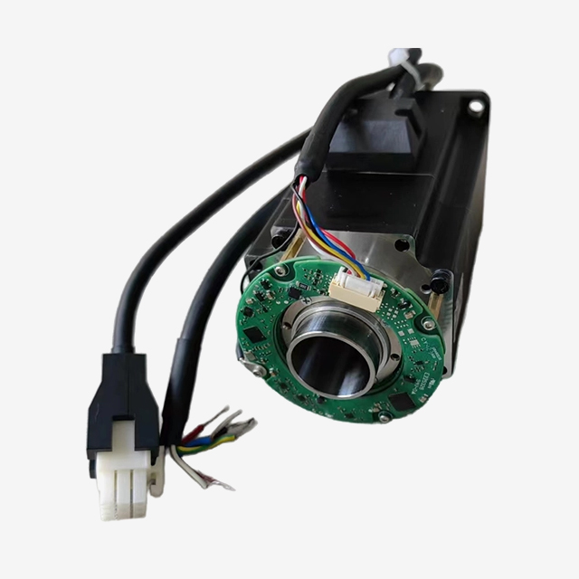
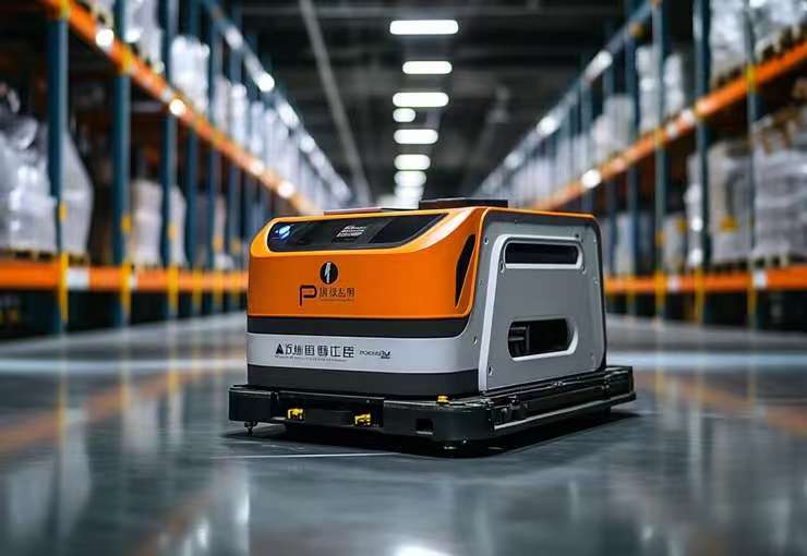
Low-voltage servo motors for automated sorting systems can provide controlled position, speed, and torque for compact sorting mechanisms. Applications may include diverter arms, steerable rollers, short transfer belts, and parcel-gapping modules.
Their value depends on the motion task and system design. A nominal 24V or 48V supply does not establish payload capacity, positioning accuracy, or sorting throughput.
For equipment builders, the selection process should connect the mechanical load, production cycle, motor-drive combination, and DC power architecture. This guide explains the main decisions and the information needed before requesting a quotation.
Table of Contents
Toggle
Where Low-Voltage Servos Fit in Automated Sorting
Match the motor to the sorting mechanism
Different mechanisms place different demands on the motor.
Sorting function
Motion requirement
Important checks
Diverter arm
Move to a commanded angle and return
Load inertia, travel time, impact, and settling
Steerable roller
Change roller orientation
Steering torque, angular position, and linkage play
Gapping conveyor
Change belt speed to adjust parcel spacing
Acceleration, available traction, sensing, and timing
Transfer or cross-belt module
Move a parcel across a short belt
Load, belt resistance, transfer time, and product slip
Tray-tilting mechanism
Position a loaded tray
Gravity torque, center of mass, and holding requirements
Not every motor in a sorter performs servo positioning. Continuous transport or accumulation zones may use other drive technologies that satisfy their requirements.
Likewise, an entire sorter’s performance cannot be inferred from one actuator. Scanning, tracking, parcel spacing, mechanical transfers, and control timing also affect sorting results.
Understand what feedback can control
A servo drive uses feedback to regulate motion within the system’s operating limits. Motor-shaft feedback does not directly measure parcel position or detect every downstream mechanical error.
A parcel can slip on a belt even when motor speed tracks its command. A diverter linkage can have play even when the motor reaches the correct angle.
Evaluate the complete mechanism, including transmission compliance, sensors, contact conditions, and load variation. Define acceptable position error, settling time, and sorting success criteria before selecting hardware.
Compare alternatives fairly
Electric servos, motorized rollers, pneumatic actuators, and other drive systems each have suitable applications.
A servo may be useful when programmable movement and feedback are valuable. A simpler actuator may be sufficient for a fixed motion with less demanding timing requirements.
Compare installed cost, energy use, maintenance, controllability, and recovery behavior using the actual production duty. Low-voltage servo operation does not automatically eliminate cabinets, pneumatic equipment, or maintenance.
Choosing Between 24V and 48V Servo Systems
Voltage affects current and speed capability
For DC input power:
Input current ≈ electrical input power ÷ bus voltage
At the same electrical input power, 48V requires approximately half the DC current of 24V. This can reduce distribution losses for the same conductor resistance.
The following figures illustrate that relationship only:
Electrical input power
Current at 24V
Current at 48V
400 W
16.7 A
8.3 A
750 W
31.3 A
15.6 A
These are not motor phase-current ratings, mechanical output ratings, or cable-sizing recommendations. Actual consumption depends on efficiency, load, operating speed, auxiliary devices, and acceleration peaks.
For a given motor winding and drive, a higher supported bus voltage may provide more voltage headroom at speed. Available torque still depends on current limits, thermal capability, and the torque-speed envelope.
There is no voltage-based payload limit
A 24V system is not automatically restricted to small parcels, and a 48V motor does not have a universal maximum parcel weight.
Required torque depends on friction, acceleration, pulley or lever dimensions, incline, transmission ratio, and load geometry. A tray-tilting axis also depends on the parcel’s center of mass.
Select the voltage and motor together. Check the drive’s permitted supply range, undervoltage threshold, current capability, and overvoltage behavior.
Tiger Motion’s low-voltage servo motor range provides a starting point for reviewing available configurations. Confirm each model’s voltage, winding, feedback, and compatible drive.
Low voltage does not establish system safety
A nominal 24V or 48V supply does not automatically make the complete circuit SELV or PELV. Protective separation, grounding arrangements, fault behavior, and applicable equipment requirements also matter.
Mechanical hazards remain present at lower supply voltages. Guarding, access controls, and maintenance procedures must follow the machine’s risk assessment.
Where a drive provides Safe Torque Off, verify its documentation and intended use. STO prevents torque-producing drive operation; it does not provide electrical isolation or guarantee immediate standstill. Loads may coast or move under external forces.
Sizing Motors for Repeated Sorting Cycles
Calculate the full duty
Define the movement distance or angle, move time, dwell time, cycle frequency, and load range.
For a rotary mechanism, evaluate acceleration torque, friction, gravity effects, and external forces. Include the inertia of the motor, transmission, linkage, and payload as appropriate.
Check both peak demand and thermal duty:
Peak torque and permitted duration.
Torque available at the required speed.
RMS torque over a representative cycle.
Drive peak and continuous current.
Motor cooling and ambient conditions.
Gearbox output limits and shaft loading.
Deceleration energy and holding periods.
There is no universal response-time requirement for every sorting module. Derive the available movement window from conveyor speed, sensor location, parcel spacing, and control latency.
Evaluate inertia and mechanical compliance
Load inertia should be reflected to the motor shaft through the actual transmission. It should not be compared directly with motor mass.
A low-inertia rotor can reduce the torque needed to accelerate the rotor itself, but it does not automatically produce the best load response. Mechanical stiffness, load inertia, tuning, and the required motion all matter.
Use manufacturer-supported sizing methods rather than applying a universal inertia-ratio limit. Verify operation at both minimum and maximum loads.
Specify feedback and restart behavior
Choose feedback according to the motion range, accuracy requirement, and recovery strategy.
Single-turn absolute feedback identifies position within one revolution. Multi-turn feedback can represent a wider rotational range, but position retention depends on the specific technology and configuration.
Absolute motor feedback does not prove that a parcel remained in place after a stop. The control system may still need product detection, referencing, or a recovery sequence.
Verify a specific model rather than assuming capability
Those specifications identify a candidate for evaluation; they do not establish suitability for a particular sorter. Request the matching drive information, torque-speed curve, feedback configuration, and application limits.
Also verify the brake’s intended duty. A holding brake should not be assumed suitable for repeated dynamic stopping.
DC Power Distribution, Integration, and Validation
Plan voltage drop and simultaneous demand
A distributed sorter can have many axes accelerating at once. Calculate branch demand from the expected operating sequence and credible worst-case events.
For a simple DC supply-and-return path:
Voltage drop = current × total circuit resistance
Include cables, connectors, protective devices, and distribution components. Check voltage at the most distant drive during acceleration rather than only at the power supply.
Cable selection must consider ampacity, voltage drop, ambient temperature, installation method, and connector ratings. Do not assign a wire gauge from nominal motor power alone.
Distributed power supplies or shorter local branches may help, but their arrangement must suit the electrical design. Do not parallel supply outputs unless the equipment permits it.
Manage regenerated energy
During deceleration, mechanical energy can return to the DC bus and raise its voltage. Back EMF describes the voltage generated by a rotating motor; regenerative braking describes energy flow back into the electrical system.
Confirm how the selected drive and supply handle returned energy. Options may include an approved braking circuit, energy-storage components, a compatible shared bus, or a regenerative supply.
A shared bus can allow energy exchange between axes, but it still needs a plan for conditions in which several axes decelerate together. Do not connect drive buses or add capacitors without manufacturer guidance.
Verify decentralized-drive and network functions
An integrated motor-drive unit can reduce separate motor and feedback cabling. It may also place electronics closer to heat, dust, vibration, and moving machinery.
Distinguish an integrated drive from a motor with an attached gearbox. A geared motor does not necessarily contain drive electronics or a network interface.
Check the exact drive’s communication options, motion functions, synchronization, diagnostics, connectors, and parameter backup. EtherCAT, PROFINET, and EtherNet/IP names alone do not establish identical motion capability.
AGV and AMR drives are related low-voltage applications, but vehicle traction does not automatically match a stationary sorting actuator. Battery voltage variation and vehicle-specific requirements need separate evaluation.
Run a representative pilot test
Test one module or lane using representative parcels and the intended production sequence.
Measure movement and settling time, sorting accuracy, product slip, bus-voltage variation, peak current, and temperature after sustained cycling. Include full-load, light-load, fault, restart, and recovery conditions.
Choose environmental protection for the actual exposure. An ingress-protection rating does not establish cold-storage suitability, chemical resistance, or hygienic cleanability.
Use measured uptime, maintenance, energy, and sorting results to assess value. Brushless construction removes brush wear, but bearings, seals, gears, cables, and connectors still require attention.
Frequently Asked Questions
1. Is 48V always better than 24V for sorting equipment?
No. At the same electrical input power, 48V reduces DC current, but the choice also depends on motor winding, speed, drive compatibility, distribution, and the installed system.
2. What payload can a low-voltage servo motor handle?
There is no universal weight limit. Calculate the torque, speed, inertia, friction, geometry, and duty of the mechanism, then verify the selected motor and transmission.
3. Does a low-voltage servo have an integrated drive?
Not necessarily. Some motors require a separate drive. Others combine the motor, feedback, and electronics. Confirm the product configuration and supported interfaces.
4. Can the motor run continuously in a sorting system?
It can if continuous torque, speed, cooling, and drive limits are satisfied. Repeated start-stop cycles also require checking peak duration, RMS torque, and regenerated energy.
5. What information is needed for a quotation?
Provide the mechanism type, load range, motion distance or angle, move and dwell times, cycle rate, transmission, supply range, controller model, environment, and installation dimensions.
Discuss Your Sorting Axis Requirements
Selecting a motor for a diverter, gapping module, or transfer mechanism? Share your load, movement profile, supply voltage, control interface, and installation requirements with Tiger Motion.
Contact Tiger Motion to discuss available motor options and request model-specific technical information. Identify any feedback, brake, environmental, or integrated-drive requirements for review.