Shrinking geometries in modern semiconductor nodes leave zero margin for error. When you process sub-5nm and sub-3nm architectures, you demand unprecedented accuracy from every machine component. Wafer positioning, optical inspection, and lithography require absolute mechanical perfection. Instability in the motion system directly compromises your critical production metrics. Vibration, thermal drift, and slow settling times destroy wafer yield. They reduce manufacturing throughput and drive up scrap rates. Selecting the right Motion Control Solutions requires moving far beyond basic specification sheets. Engineering teams must evaluate dynamic performance under shifting payloads. You must verify strict cleanroom compliance and ensure seamless integration with advanced metrology. Furthermore, evaluating a vendor's ability to scale manufacturing ensures long-term production stability. Hardware, software, and electronics must operate as a unified, deterministic system to hit wafers-per-hour targets without sacrificing nanometer-level precision.
Key Takeaways
Yield Protection is Paramount: Nanometer-level precision and active vibration mitigation directly dictate defect rates in high-density wafer processing.
Throughput vs. Precision Trade-offs: The most effective motion architectures balance rapid point-to-point movement with ultra-low settling times to maximize wafers-per-hour (WPH) without sacrificing accuracy.
Environmental Constraints Dictate Design: Cleanroom (ISO Class 1-3) and ultra-high vacuum (UHV) requirements severely limit material selection, lubrication, and thermal management strategies in motion systems.
Software and Control are Differentiators: Hardware alone is insufficient; modern solutions rely on hybrid approaches combining iterative learning control (ILC) and AI-based models to compensate for dynamic disturbances in real-time.
Table of Contents
Toggle
Key Performance Goals for Semiconductor Motion Systems
Front-End vs. Back-End Demands
Motion requirements shift drastically across the fabrication lifecycle. Front-end lithography requires continuous, ultra-smooth scanning. Constant velocity is an absolute requirement during wafer exposure. Even microscopic velocity ripples distort circuit patterns on the resist. The stage must glide flawlessly while maintaining nanometer-level alignment between the reticle and the wafer. We often see engineering teams struggle with synchronization, as the reticle stage typically moves at four times the speed of the wafer stage in opposite directions to cancel out reaction forces.
Conversely, back-end processes demand violent acceleration. Advanced packaging, wire bonding, and final test applications rely on aggressive step-and-settle profiles. The stage must move rapidly between die locations, stop instantly, and hold a rigid position. High-acceleration moves induce severe structural vibrations in the machine frame. The system must damp these vibrations within milliseconds to begin the next operation, or you risk massive throughput bottlenecks.
How to Measure Motion System Performance
Evaluating system capability requires defining strict, measurable performance indicators. Bi-directional repeatability ensures the stage returns to the exact same coordinate from any direction, which is vital for overlay alignment. Following error measures the real-time deviation between the commanded trajectory and the actual position during dynamic movement. Velocity stability dictates the smoothness of scanning operations, often measured as a percentage of the target speed. Nanometer-scale resolution determines the smallest possible incremental movement the controller can execute. These metrics define the baseline for acceptable performance in high-density fabrication.
Performance Metric
Front-End Application Focus
Back-End Application Focus
Primary Engineering Challenge
Velocity Stability
Critical (Lithography scanning)
Low priority
Eliminating motor cogging and bearing friction
Settling Time
Moderate priority
Critical (Wire bonding, inspection)
Damping structural resonances quickly
Following Error
Critical (Dynamic tracking)
Moderate priority
High-frequency servo loop updates
Bi-directional Repeatability
Critical (Overlay alignment)
Critical (Die placement)
Managing thermal drift and hysteresis
The Cost of Downtime
High-volume manufacturing environments rely on continuous, uninterrupted operation. Motion system failures halt entire production lines, causing severe bottlenecks. Calibration drift ruins entire batches of expensive wafers before metrology tools even detect the error. Unplanned maintenance forces catastrophic delays in production schedules. Equipment reliability directly dictates fab output. Systems must maintain volumetric accuracy over millions of cycles without intervention. Degradation in positioning accuracy leads to immediate yield loss. Robust mechanical design, combined with predictive maintenance algorithms, prevents these catastrophic failures and keeps the line moving.
Main Types of Precision Motion System Designs
Air Bearing Stages vs. Mechanical Bearings
Structural design dictates ultimate performance capabilities. Air bearings offer completely frictionless travel. A thin film of compressed air separates the moving carriage from the base. This eliminates mechanical wear and prevents particle generation entirely. Air bearings provide exceptional velocity stability, making them the gold standard for ISO Class 1 cleanrooms and front-end scanning applications. However, they require a continuous, highly filtered air supply and are highly sensitive to pressure fluctuations.
Mechanical cross-roller bearings provide massive load capacity and exceptional structural stiffness for high-payload applications. Modern mechanical bearings utilize advanced retainers to prevent cage creep during high-acceleration short strokes. Despite these advancements, mechanical bearings still introduce friction. This friction generates microscopic velocity ripples and potential particulate contamination, requiring specialized vacuum-compatible greases that resist outgassing.
Feature
Air Bearing Stages
Mechanical Cross-Roller Bearings
Friction Level
Zero (Non-contact)
Low to Moderate (Rolling contact)
Velocity Ripple
Extremely Low
Noticeable at low speeds
Cleanroom Suitability
ISO Class 1 (No particle generation)
ISO Class 3-5 (Requires specialized grease)
Load Capacity
Moderate (Dependent on surface area)
Extremely High
Maintenance
Requires clean air supply monitoring
Requires periodic re-lubrication
Direct Drive Motors, Piezoelectric Actuators, and Servo Drives
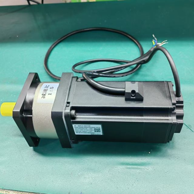
Linear and rotary direct drive motors eliminate mechanical backlash. They couple the payload directly to the electromagnetic force generator. This removes belts, ballscrews, and gears from the drivetrain. Ironless linear motors are particularly useful here, as they exhibit zero cogging torque, ensuring perfectly smooth scanning. Direct drives maximize mechanical stiffness and improve servo bandwidth. Piezoelectric actuators handle ultra-fine positioning. They utilize crystalline expansion to achieve sub-nanometer resolution. Piezo systems also provide active vibration cancellation during critical exposures.
Servo drives deliver the necessary power density to drive these motors. Engineers must select drives that minimize Electromagnetic Interference (EMI). Excessive EMI disrupts adjacent metrology equipment and corrupts high-resolution sensor data. High-performance drives require integrated cooling channels to manage their thermal footprint. Heat dissipation prevents thermal expansion in the machine frame, which would otherwise warp the coordinate system.
Advanced Metrology and Feedback Integration
Closing the position loop requires exceptional feedback mechanisms. High-resolution linear encoders and laser interferometers provide real-time position data to the controller. Optical encoders utilize diffraction principles to achieve picometer-level resolution. We often specify Zerodur or Invar scales because their near-zero coefficient of thermal expansion prevents measurement drift during temperature fluctuations.
Sensor placement is just as critical as sensor quality. Feedback sensors must measure the actual point of interest. Measuring position at the motor introduces Abbe error. Abbe error amplifies angular deviations over a given distance. If the stage pitches or yaws even slightly, the error at the wafer surface is magnified. Mounting interferometers directly at the wafer chuck eliminates this mechanical compliance. This ensures the controller receives accurate, real-world coordinate data.
Main Factors to Assess Motion System Suppliers
Nanometer-Level Positioning and Dynamic Stability
In-position jitter destroys exposure clarity during lithography. Dynamic following errors ruin high-speed optical inspection. Systems must maintain absolute stability under dynamic loads. Structural stiffness plays a massive role in dynamic stability. Stage materials must possess high specific stiffness to resist deformation. Silicon Carbide and Alumina ceramics dominate high-end applications because they push structural resonant frequencies higher. Higher resonant frequencies allow controllers to utilize higher gain settings without causing instability. This improves overall control bandwidth and reduces dynamic following errors during aggressive maneuvers.
High-Speed Throughput and Settling Time
Throughput dictates fab profitability. The motion system must execute aggressive acceleration profiles safely. It must then settle into a nanometer error band in mere milliseconds. Milliseconds saved per movement compound into massive throughput gains over a production shift. Advanced trajectory planning minimizes mechanical jerk. Jerk represents the rate of change of acceleration. High jerk excites the machine frame and induces residual vibrations that take time to damp out. Smooth, jerk-limited trajectory generation, such as S-curve profiling, prevents these vibrations. This allows the stage to settle faster and begin processing sooner.
Cleanroom and Vacuum Environment Compatibility
Semiconductor processes operate in extreme environments. Material outgassing contaminates ultra-high vacuum (UHV) chambers, coating optics and ruining wafers. Standard plastics, adhesives, and greases are strictly prohibited. Vacuum-compatible components are absolutely mandatory. Engineers must specify specialized cables, non-magnetic materials, and bake-out ready assemblies. Cable management systems often cause particle shedding. Continuous flexing degrades standard cable jackets over time. Trackless cables and flat flex designs prevent this degradation. They ensure continuous Motion without compromising ISO Class 1-3 cleanroom standards.
Advanced Control Algorithms and AI Integration
Hardware capabilities peak without advanced software control. High-frequency servo update rates, often exceeding 4kHz on EtherCAT networks, are essential for nanometer precision. Motion controllers require advanced notch filters to suppress specific mechanical resonances in the machine frame. Low-pass filters eliminate high-frequency noise from sensor data. Iterative Learning Control (ILC) eliminates repetitive tracking errors. ILC analyzes previous motion cycles and pre-compensates for known disturbances.
Emerging hybrid models integrate AI-based algorithms. Neural networks complement deterministic control signals. AI models predict thermal drift based on operating parameters like motor current and ambient temperature. They apply real-time compensation to maintain volumetric accuracy. AI also enables predictive maintenance by analyzing motor current signatures for early signs of bearing wear, alerting technicians before a failure occurs.
Vendor Scalability and "Copy Exact" Manufacturing
Prototyping a single precision stage is vastly different from high-volume production. Vendors must offer comprehensive manufacturing services. They must transition seamlessly from custom engineering to global deployment. The semiconductor industry relies on strict "Copy Exact" methodologies. Every delivered system must perform identically. A stage installed in Taiwan must match a stage installed in Arizona perfectly. Vendors must demonstrate rigorous supply chain control. They must utilize automated testing, comprehensive documentation, and strict revision control to guarantee this uniformity across all global sites.
System Design Trade-offs
Custom Engineered Solutions vs. COTS Components
Engineering teams constantly weigh custom designs against standard components. Custom multi-axis gantries require significant upfront engineering. They carry longer lead times and demand extensive validation testing. However, custom designs optimize mass, stiffness, and thermal management for specific payloads. They allow engineers to integrate cooling channels and cable routing directly into the structural castings.
Commercial Off-The-Shelf (COTS) stages offer faster deployment. They utilize proven, standardized components. Integrating stacked COTS stages often introduces alignment challenges. Stacking stages compounds angular errors and reduces overall system stiffness because of the bolted interfaces. Process uniqueness dictates the correct path. Standard automation components work well for basic wafer handling and EFEM integration. Complex optical inspection and lithography demand custom-engineered platforms to hit performance targets.
Maintenance, Lifespan, and Calibration Realities
All mechanical systems degrade over time. Friction causes wear in cross-roller bearings and ballscrews. This wear increases backlash and degrades bi-directional repeatability. Non-contact systems offer a theoretical infinite lifespan. Air bearings and direct drive motors eliminate mechanical friction entirely. However, these systems require strict environmental controls to prevent contamination of the air gap.
Regardless of the architecture, volumetric accuracy drifts over time. Thermal cycling and structural settling alter machine geometry. Systems require frequent laser calibration. Engineers must perform structural mapping using laser interferometers to update error compensation tables in the controller. This maintains precision over the equipment's operational lifecycle and ensures the tool matches its original factory calibration.
Implementation Risks and Solutions
Integration with Existing Equipment Architectures
Retrofitting new controllers into legacy equipment introduces massive risks. Communication protocols must align perfectly. Modern systems utilize EtherCAT or PROFINET for deterministic, high-speed communication. Legacy equipment may rely on outdated analog signals or slower serial buses. Latency issues destroy multi-axis synchronization. Seamless handoffs between precision stages and broader automation systems are critical. Equipment Front End Modules (EFEMs) and wafer handling robotics must sync perfectly with the main stage to prevent wafer collisions.
Hardware-in-the-loop (HIL) simulation prevents deployment failures. Engineers must mandate comprehensive API evaluation prior to procurement. Testing communication handshakes in a simulated environment eliminates integration surprises on the fab floor.
Mitigating Vibration, EMI, and Environmental Interference
External environmental factors easily ruin nanometer precision. Floor vibrations couple directly into the machine frame. Acoustic noise from cleanroom HVAC systems disrupts sensitive metrology. Drive-induced EMI corrupts high-resolution encoder signals. Mitigation requires a facility-wide engineering approach. Specify active vibration isolation systems to decouple the machine from the floor. Mandate strict environmental site surveys during the installation phase. Measure floor vibration against standard VC-E or VC-F curves to ensure compliance. Require shielded, low-noise drive architectures. Proper grounding and cable segregation protect signal integrity from high-voltage switching noise.
Conclusion
Successful semiconductor motion architectures require rigorous engineering discipline. Mechanics, electronics, and software must be co-engineered to eliminate dynamic errors. Isolating one component compromises the entire system. Engineering teams must evaluate vendors based on verifiable cleanroom certifications and proven dynamic performance under actual payload conditions.
To ensure successful deployment, execute the following steps:
Define your exact payload masses, centers of gravity, and maximum throughput constraints before engaging vendors.
Request comprehensive dynamic simulation data based on specific step-and-settle profiles.
Mandate proof-of-concept testing under actual payload and thermal conditions.
Conduct environmental site surveys to quantify floor vibration and acoustic noise levels.
Verify the vendor's "Copy Exact" manufacturing protocols and global support infrastructure.
FAQ
Q: Why is precision motion control critical for semiconductor yield?
A: Positioning errors directly degrade overlay accuracy during lithography. If wafer layers do not align perfectly, the resulting circuits fail. Nanometer-level precision prevents these defects, directly protecting wafer yield and maximizing the number of functional chips per batch.
Q: What is the difference between mechanical bearings and air bearings in semiconductor applications?
A: Mechanical bearings use physical rollers, offering high stiffness but introducing friction and particle generation. Air bearings float on a frictionless cushion of air. They eliminate wear and particle generation, making them ideal for ultra-high precision scanning in ISO Class 1 cleanrooms.
Q: How does settling time affect semiconductor manufacturing throughput?
A: Settling time is the delay required for structural vibrations to damp out after a fast movement. Saving just milliseconds during thousands of step-and-measure processes compounds rapidly. Faster settling directly increases the total number of wafers processed per hour.
Q: What are the cleanroom requirements for motion control solutions?
A: Systems must meet ISO Class 1-3 standards. This requires low-outgassing materials, specialized trackless cable management, and enclosed or frictionless drives. Standard lubricants and plastics are banned to prevent particle shedding and molecular contamination.
Q: How is AI being used in semiconductor motion control?
A: AI algorithms complement traditional control loops by predicting thermal drift and compensating for it in real-time. AI also enhances predictive maintenance by analyzing motor current data to detect microscopic bearing wear before catastrophic failure occurs.
Q: What is Abbe error and why does it matter in wafer positioning?
A: Abbe error is an angular positioning error that amplifies as the distance from the measurement axis increases. In wafer positioning, mounting feedback sensors far from the actual wafer chuck introduces microscopic deviations. Advanced metrology placement eliminates this offset.