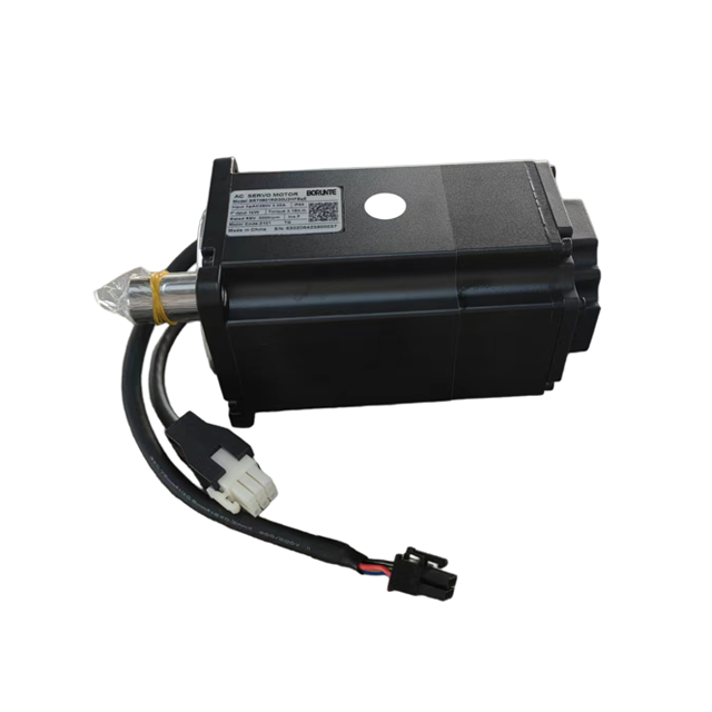
A servo system’s bus voltage dictates its absolute performance limits, thermal efficiency, and infrastructure requirements. Mis-specifying voltage classes introduces severe operational risks to machinery. Engineers often face bottlenecked top speeds due to back-EMF limitations, excessive cable weight, and massive I⊃2;R thermal losses in high-power low-voltage systems. Conversely, over-specifying high-voltage systems for simple applications introduces unnecessary safety compliance burdens and heavy insulation requirements. Evaluating a High Voltage Servo Motor Vs Low Voltage Servo Motor requires a strict technical framework. You must analyze torque-speed requirements, power source availability, dynamic load stability, and application-specific constraints. This guide breaks down the engineering differences to help you specify the correct architecture, optimize thermal management, and ensure long-term dynamic stability in your motion control applications.
Speed and Back-EMF: Higher bus voltage directly correlates to higher achievable speeds for a given motor winding before back-EMF limits performance.
Current and Thermal Efficiency: For equivalent mechanical power output, high voltage systems draw proportionally lower current, minimizing I⊃2;R losses and allowing for smaller gauge cabling.
Application Dictates Architecture: Low voltage servos (typically 24V–72V DC) are the standard for battery-powered mobile robotics (AGVs/AMRs), while high voltage servos (200V–480V AC) dominate stationary, high-torque industrial automation.
Drive Matching is Critical: Mismatching voltage ratings between motors and drives can lead to severe insulation breakdown, voltage spikes, or crippled torque-speed curves.
Safety and Compliance: High voltage systems require strict adherence to electrical safety standards, enhanced insulation, and specialized enclosures, impacting total installation cost.
Table of Contents
Toggle
Defining the Voltage Classes in Servo Systems
What Is a Low-Voltage Servo Motor
Low voltage servo systems operate within standardized direct current (DC) ranges. You will typically see these rated for 12V, 24V, 48V, and up to 72V DC. These systems rely entirely on direct current power supplies or localized battery arrays rather than facility mains power. The architecture is built around safe-to-touch voltage levels. This inherently limits the electrical potential available to drive the motor windings.
From a physical standpoint, low voltage motors feature highly compact, high-torque-density designs. Because they operate at lower potentials, the internal dielectric insulation surrounding the copper windings is thin. Manufacturers can pack more copper into a smaller stator volume. This optimizes the motor for space-constrained environments. You will frequently find these motors in custom form factors, frameless designs, or highly integrated modules where the drive and motor share a single compact housing. They are engineered specifically for applications where onboard energy storage dictates the electrical architecture. Think of automated guided vehicle (AGV) wheel drives or robotic joints where space is at an absolute premium.
The reliance on battery arrays means these motors must operate efficiently within the discharge curves of common battery chemistries. A 48V nominal lithium-iron-phosphate (LiFePO4) battery might drop to 42V under heavy load. The low voltage servo motor must be wound to deliver its rated torque even when the DC bus sags during these discharge cycles.
What Is a High-Voltage Servo Motor
High voltage servo systems operate on alternating current (AC) mains power. They utilize standard industrial voltage ranges such as 200V, 230V, 400V, 460V, and 480V AC. Unlike their low voltage counterparts, these systems require a servo drive equipped with a robust rectifier bridge. The rectifier converts the incoming multi-phase AC mains power into a high-voltage DC bus. The drive's inverter section then modulates this DC bus to control the motor phases.
The structural differences in a High Voltage Servo Motor are significant. To withstand the high electrical potential and the rapid voltage switching generated by modern pulse-width modulated (PWM) drives, these motors require heavy dielectric insulation. They utilize thicker slot liners, phase separators, and advanced potting compounds. Consequently, they are built in larger, standardized frame sizes, such as NEMA or metric equivalents.
The robust construction includes advanced thermal dissipation designs. You will see heavy extruded aluminum housings or active cooling fans to manage the continuous power output required in heavy industrial automation. The insulation class is typically rated for Class F or Class H, allowing the internal windings to safely reach temperatures up to 155°C or 180°C without degrading the dielectric strength. This thermal headroom is mandatory for continuous duty cycles in factory environments.
High Voltage Servo Motor Vs Low Voltage Servo Motor: Core Engineering Differences
Speed, Torque, and Bus Voltage Dynamics
The relationship between bus voltage and motor speed is a non-negotiable law of electromagnetics. A lower bus voltage inherently reduces the top speed of a servo system, even if the motor's bearings and mechanical components are rated for much higher RPMs. This limitation is driven by back-Electromotive Force (back-EMF).
As a servo motor spins, its permanent magnets rotate past the stator windings. The motor acts as a generator. This generates a voltage that opposes the supply voltage provided by the drive. The faster the motor spins, the higher the back-EMF. When the back-EMF approaches the available bus voltage, the drive can no longer push current into the motor windings. Without current, the motor cannot produce torque.
A high voltage system provides a massive overhead of electrical potential. It easily overcomes back-EMF to maintain flat, consistent torque delivery at exceptionally high RPMs. If you examine the torque-speed curves of low voltage systems, you will notice a sharp drop-off point where torque plummets as speed increases. This directly illustrates the voltage bottleneck. A 48V motor might hit a wall at 2,000 RPM, while a 400V motor with similar mechanical dimensions can push flat torque past 5,000 RPM.
Current Draw, Power Equations, and the Hobbyist Misconception
Understanding the power equation is mandatory when evaluating these two architectures. To achieve high mechanical power output with a low voltage supply, the system must draw massive amounts of current. Generating 2,000 watts of mechanical power at 48V requires over 41 amps of continuous current. Generating that same 2,000 watts at 400V requires only 5 amps.
There is a persistent misconception originating from the hobbyist and remote-control sectors regarding current draw. In the RC world, "high voltage" often refers to pushing a motor past its nominal ratings to extract maximum burst power. This results in drawing significantly more current. In professional industrial engineering, the opposite is true. An engineered high voltage system draws substantially less current for the exact same mechanical power output compared to a low voltage equivalent.
This difference in current draw has profound dynamic and thermal implications. Heat generation in electrical systems scales exponentially with current due to I⊃2;R losses. The higher continuous and peak currents in low voltage systems lead to rapid heat accumulation in both the motor windings and the drive's switching components. You must implement aggressive thermal management to prevent overheating.
Cabling, Wiring, and Infrastructure Footprint
The physical impact of current requirements directly dictates your infrastructure footprint. High current necessitates thick, heavy copper conductors to prevent the cables themselves from acting as heating elements. In low voltage systems pushing high power, the sheer thickness of the required cables becomes a mechanical liability.
When you pull cables through a drag chain on a multi-axis machine, cable weight matters. A 48V system pushing 2kW requires heavy 8 AWG wire. Bending that repeatedly at high speeds causes mechanical fatigue and eventual failure. A 400V system doing the same work uses 18 AWG wire. It flexes easily and lasts millions of cycles. High voltage systems utilize significantly thinner, lighter cables because their current draw is a fraction of their low voltage counterparts.
This reduction in copper provides major mechanical advantages. It drastically reduces drag and mechanical wear inside dynamic cable tracks. It lowers the moving mass on robotic arms, improving overall system responsiveness. It simplifies routing through tight machine chassis. However, high voltage cables require much thicker, highly specialized dielectric insulation to prevent arcing, manage electromagnetic interference (EMI), and ensure compliance with industrial safety standards.
Performance Assessment & Application Matching
When to Specify Low Voltage Servos
Low voltage servos are the standard for applications where mobility and onboard power storage are the primary constraints. They are engineered specifically to integrate seamlessly with direct current sources. You will find them in environments where tethered power is impossible.
Autonomous Mobile Robots (AMRs) used in logistics and fulfillment.
Portable medical devices requiring precision motion without tethered power.
Remote inspection equipment operating in off-grid environments.
Agricultural robotics operating in open fields on battery power.
In these battery-operated systems, low voltage is an absolute necessity. Attempting to invert battery DC power into high-voltage AC power is electrically inefficient. It adds massive weight through heavy inverters and consumes valuable physical space. Low voltage architectures provide a distinct advantage in environments requiring safe-to-touch electrical systems. Operating below 60V DC generally qualifies as Safety Extra Low Voltage (SELV) or Protective Extra Low Voltage (PELV). This drastically reduces the need for heavy physical guarding and complex personnel safety protocols.
When to Specify High Voltage Servos
High voltage servos dominate heavy industry, stationary automation, and applications requiring extreme dynamic performance. They are designed to leverage the existing electrical infrastructure of modern manufacturing facilities. You specify these when you have access to grid power and need maximum mechanical output.
Multi-axis CNC machining centers cutting hard metals.
Heavy payload industrial robotic arms used in automotive welding.
Stationary automated assembly equipment.
Large-scale material handling gantries.
These applications rely on facility mains power, typically 3-phase AC. Distributing high voltage across a large factory floor is highly efficient. It minimizes voltage drop over long cable runs. The most significant advantage of high voltage in these settings is the ability to execute rapid acceleration and deceleration of massive loads. Because the current draw remains relatively low even during peak power transients, the system can perform aggressive motion profiles without tripping overcurrent protections or causing localized power grid sags.
Drive Matching, Stability, and System Architecture Trade-Offs
Power Supply Stability and Rectification Requirements
The architecture of the servo drive itself changes drastically depending on the voltage class. High voltage drives are complex power conversion units. They require robust internal rectification circuits to convert the incoming 3-phase AC mains into a stable, high-voltage DC bus. This rectification stage requires heavy-duty diodes, large heat sinks, and substantial internal filtering. This inherently increases the physical size and footprint of the drive inside the electrical cabinet.
Low voltage drives feature simpler power stages because they operate directly from an external DC supply or battery. They do not need AC-to-DC rectifiers. This simplicity shifts the engineering burden elsewhere. Low voltage drives require massive internal capacitor banks. These capacitors are critical for handling regenerative energy and preventing severe voltage sag during high-torque transients. If the DC power supply cannot respond fast enough to a sudden current demand, the capacitors must bridge the gap to prevent the drive from faulting out due to under-voltage.
Avoiding Common Motor-Drive Mismatch Mistakes
Mismatching voltage ratings between motors and drives is a catastrophic engineering error. You must ensure strict compatibility between the drive's output characteristics and the motor's insulation class.
Pairing a low voltage motor with a high voltage drive is the most dangerous mismatch. Low voltage motors lack the thick dielectric insulation required to withstand high electrical potentials. When subjected to the high voltage and the rapid voltage switching (high dv/dt) of an AC drive, the motor's internal insulation will rapidly break down. This causes corona discharge and ozone generation inside the motor housing. The ozone eats the thin enamel on the copper wire. This leads to immediate short circuits between the phase windings or from the windings to the motor casing, permanently destroying the stator.
Running a high voltage motor on a low voltage drive will not destroy the motor, but it incurs a massive performance penalty. Because the drive cannot supply enough voltage to overcome the motor's back-EMF, the system suffers from severe speed bottlenecking. The motor will be entirely incapable of reaching its rated RPM or delivering its rated mechanical power. The system becomes practically useless for dynamic applications.
Managing Regenerative Energy
Whenever a servo system decelerates a load, the motor acts as a generator. It pushes kinetic energy back into the electrical system as reverse current. Managing this regenerative energy requires completely different strategies depending on the voltage class.
In high voltage systems, the drive's DC bus absorbs this energy, causing the bus voltage to rise. To prevent over-voltage faults, high voltage drives utilize built-in braking choppers. These choppers route the excess energy into heavy-duty bleeder resistors, dissipating it as heat. In highly advanced, multi-axis systems, regenerative power supplies can invert this energy and push it back into the facility's AC mains grid. This improves overall plant efficiency.
In low voltage, battery-powered systems, regenerative energy is routed back into the battery array. While this recharges the battery, it presents a significant risk. Batteries have strict charge acceptance limits. If the deceleration is too aggressive, the returning energy will spike the system voltage. This can over-voltage the battery management system (BMS) or destroy the drive. Low voltage systems often require specific voltage clamping circuits or external dump resistors to safely burn off excess energy when the battery cannot absorb it fast enough.
Risks During Use and Daily Efficiency
Safety Compliance and Isolation Requirements
Deploying high voltage systems introduces stringent regulatory burdens and safety compliance requirements. Operating machinery at 400V or 480V AC falls under strict industrial safety directives, including OSHA regulations, NFPA 79, and IEC 60204-1 standards. These regulations dictate every aspect of the machine's electrical design.
Engineers must implement mandatory lock-out/tag-out (LOTO) procedures to ensure the system is completely de-energized before maintenance. High voltage systems require specialized, heavily grounded electrical enclosures with interlocked doors that prevent access while energized. Only certified electrical personnel are legally permitted to service or troubleshoot these panels. The physical isolation requirements include shielded cables, heavy-duty M23 circular connectors, and strict separation of high voltage power lines from low voltage signal wires. This adds significant complexity to the machine build.
Component Sizing vs. Operational Efficiency
When engineering a motion control system, you must balance the physical sizing of components against long-term operational efficiency. Low voltage systems demand high-amperage external power supplies. If you build a stationary machine using low voltage servos, you must source massive, heavy DC power supplies capable of delivering 50 to 100 amps continuously. Combined with the thick copper cabling required to route that current, the physical bulk of the electrical infrastructure scales poorly as mechanical power requirements increase.
High voltage systems offer vastly superior electrical efficiency at scale. Because they draw low current, the thermal management demands on the facility's electrical infrastructure are significantly lower. You do not need massive external DC power supplies. You simply connect the drives directly to the facility's AC mains through standard circuit breakers and contactors. For high-power industrial applications requiring multiple axes of synchronized motion, the operational efficiency and streamlined infrastructure of high voltage architecture provide a cleaner, more stable engineering solution.
Engineering Metric
Low Voltage Servo Motor
High Voltage Servo Motor
Typical Voltage Range
24V to 72V DC
200V to 480V AC
Primary Power Source
Battery Arrays, DC Power Supplies
Facility AC Mains (3-Phase)
Current Draw (Equal Power)
Exceptionally High
Significantly Low
Insulation Requirements
Thin (Optimized for space)
Thick (High dielectric strength)
Top Speed Limitations
Bottlenecked by early back-EMF
High overhead for maximum RPM
Regenerative Handling
Battery absorption, clamping circuits
Bleeder resistors, mains return
Ideal Applications
AGVs, AMRs, Portable Devices
CNC, Packaging, Heavy Robotics
Cable Sizing
Thick gauge (Heavy copper)
Thin gauge (Lightweight)
Conclusion
Calculate the absolute peak mechanical power and RMS torque requirements for your specific motion profile to determine baseline current demands.
Map your required torque-speed curve against manufacturer specifications to identify potential speed bottlenecks caused by back-EMF in lower voltage ranges.
Evaluate your facility or machine's power infrastructure to determine the feasibility of routing thick, high-amperage DC cables versus shielded AC mains wiring.
Consult directly with your servo drive manufacturer to verify exact motor-drive compatibility, ensuring you avoid catastrophic insulation breakdown risks.
Size your regenerative braking resistors or clamping circuits based on the maximum deceleration loads of your heaviest mechanical axis.
FAQ
Q: Does a high voltage servo motor draw more current?
A: No. In industrial engineering, a high voltage servo motor draws significantly less current than a low voltage motor to produce the exact same mechanical power. The misconception that high voltage means higher current comes from the hobbyist sector, where pushing voltage past nominal ratings forces higher burst power.
Q: Can I run a high voltage servo motor on a low voltage drive?
A: Yes, but with severe performance penalties. The low voltage drive will not damage the high voltage motor, but it cannot provide enough electrical potential to overcome the motor's back-EMF. This results in extreme speed bottlenecking, preventing the motor from reaching its rated RPM or power output.
Q: What happens if I use a low voltage motor with a high voltage drive?
A: This mismatch will rapidly destroy the motor. Low voltage motors lack the thick dielectric insulation required to handle high electrical potentials. The high voltage and rapid switching frequencies from the drive will cause internal insulation breakdown, leading to catastrophic short circuits.
Q: Why do low voltage servo systems experience voltage sag?
A: Low voltage systems require massive amounts of current to generate high torque. During rapid acceleration, the sudden demand for peak current can overwhelm the DC power supply or battery array. If the supply cannot deliver the current fast enough, the system voltage drops temporarily, causing a sag.
Q: Are low voltage servo motors safer to operate?
A: Yes, from an electrical shock perspective. Systems operating below 60V DC generally fall under Safety Extra Low Voltage (SELV) standards. They are considered safe-to-touch, reducing the need for the heavy guarding, specialized enclosures, and strict lock-out/tag-out procedures required for high voltage systems.
Q: How does back-EMF affect servo motor selection?
A: Back-EMF is the voltage generated by the spinning motor that opposes the supply voltage. As speed increases, back-EMF increases. If the back-EMF equals your bus voltage, the motor cannot spin faster. You must select a voltage class high enough to overcome back-EMF at your required top speed.