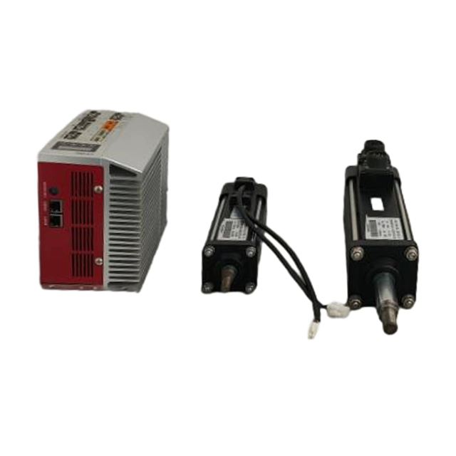
High-performance motion control relies on precise torque, velocity, and position regulation. Selecting an Industrial Servo Motor dictates the success or failure of your mechanical system. Over-specifying a motor leads to unnecessary footprint expansion and wasted energy capacity. Under-specifying results in thermal failure, poor indexing accuracy, and unacceptable machine downtime. Navigating the procurement process requires moving beyond basic horsepower ratings. You must evaluate inertia matching, feedback resolution, drive compatibility, environmental resilience, and Industry 4.0 readiness. This guide provides a framework for evaluating and shortlisting motors for automation and large-scale manufacturing applications.
Inertia Matching is Non-Negotiable: Achieving a stable load-to-rotor inertia ratio (typically between 1:1 and 5:1 for high-dynamic applications) is the most critical factor in preventing tuning instability and resonance.
Protocol Compatibility Dictates Integration: The choice of servo motor must align with existing PLC and drive architectures; proprietary ecosystems offer plug-and-play simplicity, while open protocols (e.g., EtherCAT, PROFINET) provide long-term vendor flexibility.
Feedback Mechanisms Define Precision: The application's required positioning accuracy dictates the choice between incremental encoders, absolute encoders, or rugged resolvers.
Digital Transformation Drives Value: Modern industrial servo motors equipped with predictive maintenance telemetry and single-cable technology significantly reduce lifecycle operating expenses and unplanned downtime.
Environmental Realities Trump Specs: A motor's continuous torque rating is only valid if thermal management and Ingress Protection (IP) ratings align with the actual operating environment (e.g., washdown, high ambient heat, or dust).
Table of Contents
Toggle
Core Requirements for Industrial Servo Motor Selection
Analyzing Load Characteristics
Accurate motor sizing begins with calculating the reflected inertia of all moving components back to the motor shaft. You must document the mass, friction coefficients, and external forces acting upon the mechanical system. This includes evaluating the efficiency and mechanical advantage of ball screws, timing belts, or rack and pinion mechanisms. Vertical axes introduce gravitational forces that constantly pull on the load. These vertical applications often necessitate the integration of holding brakes and require asymmetrical torque calculations for upward versus downward motion.
To properly analyze the load, engineers typically follow a strict sequence of evaluations:
Calculate the mass and inertia of the raw payload being moved.
Determine the inertia of the transmission components, including couplings, gearboxes, and lead screws.
Calculate the reflected inertia at the motor shaft, factoring in the square of the gear reduction ratio.
Identify static and kinetic friction forces present in the linear guides or rotary bearings.
Account for external opposing forces, such as cutting forces in CNC applications or fluid resistance in pumping systems.
Duty Cycle and Motion Profiles
The operational duty cycle dictates the thermal load placed on the motor windings. Mapping the required move times, dwell times, and acceleration or deceleration rates allows you to calculate the Root Mean Square (RMS) torque. The motor must handle continuous operational phases without exceeding its internal thermal limits. Trapezoidal and S-curve motion profiles impose different peak torque demands during the acceleration phase. Understanding these profiles ensures the motor provides sufficient intermittent torque without triggering drive faults.
A common mistake in field installations involves ignoring the dwell time. If a motor holds a heavy load in position without a mechanical brake, it continuously draws current. This holding current generates significant heat. You must factor this stationary heat generation into the overall RMS torque calculation to prevent premature winding insulation failure.
Precision and Repeatability Requirements
Establishing the acceptable margin of error for positioning and velocity ripple is fundamental to application success. High-precision environments like semiconductor manufacturing or multi-axis CNC machining demand exact positioning down to the micrometer or arc-second. This requirement dictates the necessary encoder resolution and the mechanical stiffness of the coupling between the motor and the load.
Mechanical compliance, backlash in gearboxes, and hysteresis must be minimized. If the mechanical transmission introduces slop, even the highest-resolution encoder will fail to position the final load accurately. You must match the motor's theoretical precision with rigid, low-backlash mechanical components to ensure the commanded position translates directly to the actual load.
Lifecycle Operating Costs and Energy Efficiency
Evaluating lifecycle operating expenses requires looking past the initial purchase order. Power consumption during continuous large-scale manufacturing often dwarfs the upfront hardware costs. High-efficiency motors paired with regenerative servo drives can capture kinetic energy during deceleration phases and feed it back into the facility's power grid or share it across a common DC bus with other motoring axes.
Energy efficiency also impacts the facility's HVAC requirements. Motors that run hot dump thermal energy into the factory environment, increasing the load on air conditioning systems. Selecting a motor with optimized magnetic designs and low copper losses directly reduces both electrical consumption and secondary cooling expenses.
Types of Industrial Servo Motor Designs
AC vs. DC Servo Motors
The choice between alternating current (AC) and direct current (DC) architectures depends heavily on the available power infrastructure and the specific dynamic requirements of the machine.
Feature
AC Servo Motors
DC Servo Motors
Power Source
High-voltage alternating current (typically 230V to 480V 3-phase).
Low-voltage direct current (typically 24V to 72V).
Speed and Torque
Capable of high speeds and massive continuous torque output.
Excellent low-speed control; limited top-end speed and torque.
Automated Guided Vehicles (AGVs), autonomous mobile robots, battery-powered systems.
Maintenance
Virtually maintenance-free (brushless designs).
Requires brush replacement (if brushed); brushless DC options exist.
Brushless vs. Brushed Designs
Brushless motors (BLDC or PMSM) represent the industry standard for modern motion control. They utilize electronic commutation via drive software and rotor position sensors rather than physical brushes. This design eliminates carbon dust generation and mechanical wear. The result is superior thermal dissipation, higher torque-to-weight ratios, and maintenance-free operation. Because the heat-generating windings are located on the stator (the outer shell), heat escapes easily into the machine frame.
Brushed motors are legacy technology. They are largely phased out of high-end industrial applications due to frequent maintenance requirements. The physical brushes wear down over time, creating conductive carbon dust that can short out internal electronics. Furthermore, the heat-generating windings are located on the spinning rotor, making thermal dissipation highly inefficient. You will only encounter brushed motors in specific retrofit scenarios or highly specialized legacy equipment.
Housed vs. Frameless Configurations
Housed motors are traditional, self-contained units featuring integrated shafts, bearings, and protective enclosures. They offer plug-and-play simplicity. You bolt them to a flange, attach a coupling, and plug in the cables. This makes them ideal for standard factory automation where quick installation and easy replacement are priorities.
Frameless motors consist solely of a rotor and stator, supplied without a housing or bearings. You design them directly into the machine's mechanical structure. The machine's own bearings support the rotor. This configuration is essential for advanced industrial design, compact robotic joints, and aerospace applications requiring minimal weight and optimized spatial footprints. Integrating frameless motors requires precise machining tolerances and a deep understanding of thermal expansion within the custom housing.
Technical Assessment: Motor Sizing & Performance
Torque and Speed Curves
Evaluating a motor requires analyzing its specific torque-speed curve. The continuous torque rating defines the motor's ability to deliver sustained rotational force indefinitely without exceeding its maximum winding temperature. Peak torque represents the motor's capacity to handle short bursts of high demand, typically required during rapid acceleration or emergency deceleration.
You must identify the base speed. This is the point at which the drive can no longer increase voltage to overcome the motor's back-electromotive force (back-EMF). Beyond the base speed, the motor enters the field weakening region, where available torque drops off sharply. The application's speed and torque requirements must fall squarely within the motor's continuous operating zone for steady-state motion, and within the intermittent zone for acceleration phases.
Inertia Ratio Matching
The ratio of load inertia to motor rotor inertia dictates system responsiveness and tuning stability. A massive load attached to a small rotor creates a high inertia ratio. This leads to overshoot, mechanical resonance, and sluggish control loops. The drive struggles to force the small rotor to control the massive kinetic energy of the load.
Direct-drive applications require very low ratios, often between 1:1 and 3:1, to achieve maximum bandwidth and rapid settling times. Systems utilizing gear reducers can tolerate higher ratios. A gearbox reduces the reflected load inertia by the square of the gear ratio. For example, a 10:1 gearbox reduces the reflected inertia by a factor of 100, allowing a relatively small motor to control a massive load stably.
Feedback and Commutation Mechanisms
The feedback device closes the control loop, providing the drive with real-time velocity and position data. The choice of feedback impacts startup procedures, precision, and environmental resilience.
Feedback Type
Operational Characteristics
Best Application Scenarios
Incremental Encoders
Tracks relative movement via quadrature pulses. Requires a homing sequence to establish a zero position upon power-up.
Standard velocity and position control where startup homing is acceptable and cost is a primary concern.
Absolute Encoders
Retains exact position data after power loss using multi-turn batteries or Wiegand wire technology. Eliminates homing.
Complex multi-axis systems, robotics, and applications with high collision risks during startup.
Resolvers
Utilizes analog rotary transformers to measure position. Contains no delicate optics or complex onboard electronics.
Extreme environments involving heavy vibration, high temperatures, shock, or radiation.
Environmental Resilience and Compliance Factors
Ingress Protection (IP) Ratings
A motor's continuous torque rating is only valid if its physical enclosure can withstand the operating environment. Standard factory environments typically require IP54 or IP65 ratings, providing robust protection against dust ingress and low-pressure water jets. If you place an IP54 motor in a wet environment, fluid will bypass the shaft seal, short out the encoder, and destroy the stator windings.
Harsh environments demand IP67 or IP69K ratings. Food and beverage washdown zones, pharmaceutical manufacturing, and heavy machining centers expose motors to high-pressure, high-temperature caustic cleaning fluids. Motors in these environments feature specialized PTFE shaft seals, food-grade epoxies, and smooth stainless-steel housings designed to prevent bacterial accumulation and withstand daily chemical washdowns.
Thermal Management and Cooling
Motors generate heat through copper losses in the windings and iron losses in the stator core. Natural convection cooling relies on ambient air and the metallic machine frame acting as a heatsink. If the ambient temperature is exceptionally high or the physical space is confined, the motor's ability to dissipate heat decreases. You must derate the continuous torque specification to prevent thermal overload.
Forced air cooling via external fans becomes necessary to maintain performance in high-ambient conditions. The fan provides a constant flow of ambient air over the motor's cooling fins. Liquid cooling jackets are reserved for ultra-compact, high-power-density applications. In these scenarios, air cooling simply cannot remove heat fast enough, requiring chilled water or glycol mixtures to circulate through the motor housing.
Certifications and Hazardous Locations
Global deployment requires strict compliance with international safety and performance standards, including UL, CE, and CSA. Failing to specify motors with the correct regional certifications will result in failed inspections and delayed machine commissioning.
Applications located in hazardous environments with combustible dust, flammable gases, or volatile vapors require specialized explosion-proof motors. These units must be certified under ATEX or IECEx directives. Explosion-proof motors feature heavily reinforced housings and precise flame paths. They are not designed to keep explosive gases out; rather, they are designed to contain any internal electrical explosion and cool the escaping gases before they can ignite the surrounding external atmosphere.
Servo Drive Matching and System Trade-offs
Amplifier and Controller Compatibility
Pairing a motor with a servo drive from the same manufacturer guarantees performance specifications and dramatically simplifies commissioning. Matched sets utilize auto-recognition features. The drive automatically reads the motor's electronic nameplate, instantly configuring commutation angles, current limits, and baseline tuning parameters. This plug-and-play functionality saves hours of engineering time per axis.
Mixing vendors offers hardware independence but requires manual configuration of all feedback parameters and tuning loops. You must manually input the motor's inductance, resistance, back-EMF constant, and pole pair count into the third-party drive. This increases integration time and places the burden of performance validation entirely on the system integrator. If the system oscillates or fails to reach peak torque, neither the motor vendor nor the drive vendor will take responsibility.
Communication Protocols
Multi-axis synchronization relies heavily on the communication protocol bridging the PLC and the servo drives. Deterministic Ethernet protocols like EtherCAT, PROFINET IRT, and EtherNet/IP provide microsecond-level jitter and distributed clock synchronization. This is mandatory for precise coordination in printing presses, packaging lines, and multi-axis robotics where multiple motors must move in perfect lockstep.
Legacy protocols such as CANopen or Modbus RTU remain highly relevant for simpler, point-to-point indexing applications. They are also necessary when integrating new motion axes into older, established PLC architectures that lack modern Ethernet capabilities. However, these serial protocols lack the bandwidth required for high-speed, synchronized multi-axis interpolation.
Digital Transformation and Industry 4.0 Readiness
Modern smart drives leverage advanced motor sensors to monitor high-frequency vibration, thermal degradation in the windings, and bearing wear. This predictive maintenance telemetry allows facility operators to schedule targeted repairs during planned outages before a catastrophic failure halts production. The drive analyzes the current draw and vibration signatures, alerting the PLC when mechanical wear begins to increase friction in the system.
Single-Cable Technology (OCT) represents a major leap in physical integration. By combining heavy power conductors and sensitive digital feedback signals into a single shielded line, OCT reduces cabling complexity. It saves critical space in flexible drag chains and simplifies installation in dense mechanical designs. This technology relies on robust digital communication protocols to send encoder data over the same cable carrying high-voltage PWM power without suffering from interference.
Risks and Mitigation Strategies
Electromagnetic Interference (EMI)
High-frequency Pulse Width Modulation (PWM) switching in servo drives generates significant Electromagnetic Interference. This noise can corrupt sensitive encoder signals, leading to erratic motor behavior, position loss, or drive faults. Mitigation requires strict adherence to installation best practices.
Utilize high-quality shielded twisted-pair cables for all feedback connections.
Enforce strict physical separation between power and feedback lines in cable trays, maintaining at least 200mm of distance.
If power and signal cables must cross, ensure they intersect at a 90-degree angle to minimize inductive coupling.
Implement robust equipotential grounding techniques, grounding both ends of the cable shield with 360-degree clamps to safely shunt noise away from control electronics.
Mechanical Resonance
Structural flex in the machine frame or windup in mechanical couplings can cause severe tuning instability. When the servo drive attempts to correct a position error, mechanical compliance introduces a delay. This causes the control loop to overcompensate and induce oscillation, often resulting in a loud high-pitched squeal from the mechanics.
Engineers identify these specific resonance frequencies using Bode plots generated by the drive's tuning software. Mitigation involves applying targeted notch filters or low-pass filters within the servo drive. These filters dampen the specific frequencies causing the mechanical structure to ring, allowing you to increase the control loop gains without triggering instability.
Cable Flex Life
Continuous-motion applications like robotic arms, gantry systems, or automated cable tracks subject motor cables to millions of bending and twisting cycles. Using standard static cables in these environments guarantees premature failure of the copper conductors or the outer jacket.
Specifying continuous-flex cables with appropriate minimum bend radii and polyurethane jackets prevents this failure. Proper installation within the cable track is equally important. You must ensure cables are laid flat, not twisted, and have sufficient slack to move freely without being pulled tight during motion. Securing the cables only at the ends of the track prevents internal friction from destroying the insulation.
Supply Chain and Lifecycle Support
Large-scale manufacturing investments require reliable, long-term lifecycle support. When selecting a motor ecosystem, you must evaluate vendor lead times and the global availability of replacement parts. A highly specialized motor with a 40-week lead time introduces unacceptable risk to a production facility.
Furthermore, ensuring long-term firmware support and backward compatibility for drives protects the initial hardware investment. When a drive fails ten years after installation, you need the assurance that the vendor's current drive lineup can still communicate with the legacy motor and encoder without requiring a complete mechanical retrofit.
Conclusion
Calculate the required continuous torque, peak torque, and load-to-rotor inertia ratio based on your specific mechanical system and motion profile.
Filter potential motor candidates by their Ingress Protection (IP) ratings and thermal management capabilities to ensure they survive the actual operating environment.
Verify compatibility between the motor's feedback mechanism, the selected servo drive, and the facility's overarching industrial communication protocol.
Compile all load data and consult with a dedicated motion control engineer to validate sizing mathematics before finalizing the procurement order.
FAQ
Q: How do I calculate the required torque for an industrial servo motor?
A: Calculate the Root Mean Square (RMS) torque by analyzing the load's reflected inertia, friction coefficients, and gravitational forces. Combine this with the acceleration, continuous, and deceleration phases of your specific motion profile to determine both continuous and peak torque demands.
Q: What is the acceptable inertia ratio for a high-speed packaging machine?
A: High-speed, highly dynamic applications typically require a load-to-rotor inertia ratio between 1:1 and 5:1. This low ratio ensures high control bandwidth, rapid settling times, and prevents mechanical resonance during aggressive acceleration and deceleration phases.
Q: What is the difference between an absolute and incremental encoder in servo applications?
A: Absolute encoders retain exact position data even after a complete power loss, allowing the machine to resume operation immediately. Incremental encoders only track relative movement and require the machine to execute a homing sequence to find its zero position upon power-up.
Q: What is a frameless industrial servo motor and when should I use one?
A: A frameless motor consists only of a bare rotor and stator, supplied without a housing, shaft, or bearings. They are used when engineers need to integrate the motor directly into a machine's mechanics to minimize weight and optimize space, such as in robotic joints.
Q: How does ambient temperature affect a servo motor's continuous torque rating?
A: High ambient temperatures reduce the temperature delta between the motor and the surrounding air, limiting the motor's ability to dissipate internal heat. This requires engineers to derate the continuous torque specification to prevent the internal windings from overheating.
Q: Can I pair a servo motor from one manufacturer with a drive from another?
A: Yes, mixing manufacturers is possible, but it eliminates plug-and-play simplicity. It requires manual configuration of commutation angles, feedback parameters, and tuning loops, which significantly increases integration time and engineering effort compared to using a matched set.