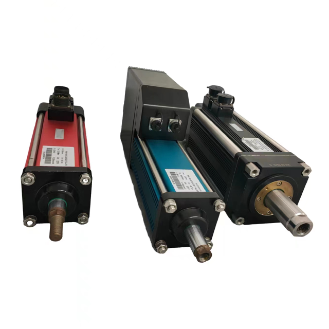
The industrial automation sector is shifting from legacy fluid power systems to advanced electromechanical motion control. Engineers and system designers face a specific engineering dilemma when specifying linear motion systems: balancing the simplicity of pneumatics against the precise control and high duty cycles of an Electric Cylinder. Choosing between these two distinct technologies requires a rigorous technical evaluation. System architects must analyze application-specific performance metrics, safety requirements, and facility infrastructure constraints. A standard pneumatic setup relies on compressed air to generate force, offering robust performance in harsh environments. Conversely, electromechanical systems utilize servo or stepper motors coupled with mechanical screws to deliver programmable, highly repeatable motion profiles. Understanding the mechanical architecture, performance limitations, and integration requirements of each technology is essential for optimizing machine design and ensuring long-term operational reliability.
Precision & Control: An electric cylinder offers infinite, programmable positioning, velocity control, and high repeatability, whereas pneumatic cylinders are generally limited to simple end-to-end positioning unless equipped with expensive proportional valves.
Safety & Load Holding: Pneumatic cylinders naturally hold load via trapped air but can drift; an electric cylinder requires electromagnetic brakes to prevent backdriving in vertical applications during power loss.
Infrastructure Dependency: Pneumatics require a centralized, maintenance-heavy compressed air network (compressors, filters, regulators, lubricators, dryers), while electric systems rely on existing electrical grids and local motor drives.
Environmental Suitability: Pneumatic cylinders excel in extreme, explosive (ATEX), or high-temperature washdown environments, whereas electric cylinders are preferred for cleanrooms, quiet operations, and contamination-sensitive food processing.
Table of Contents
Toggle
How Electric and Pneumatic Cylinders Work
The Mechanics of an Electric Cylinder
The fundamental architecture of an electromechanical actuator revolves around converting rotary motion into linear motion. This is achieved using an electric motor coupled directly or indirectly to a mechanical screw assembly. As the motor rotates, the screw turns, driving a nut attached to the extension rod forward or backward. This direct mechanical linkage allows for absolute control over the stroke length, speed, and applied force. The physical connection between the motor and the driven load eliminates the compliance found in fluid-based systems.
The type of screw transmission used dictates the performance characteristics of the actuator. Engineers must match the screw type to the specific load and duty cycle requirements of the application.
Lead Screws: These utilize sliding friction between the nut and the screw. They offer high self-locking capabilities and operate quietly, making them suitable for low duty cycles and light loads. Their high friction results in lower overall efficiency and faster wear under continuous operation.
Ball Screws: Utilizing recirculating ball bearings to reduce friction, ball screws provide medium-to-high efficiency, high speed, and long operational life. They represent the standard for most industrial automation tasks requiring reliable, continuous motion.
Roller Screws: Engineered for maximum power density, roller screws use threaded rollers instead of ball bearings. This design provides extreme load capacities, high rigidity, and superior lifespan under continuous heavy loads, often rivaling hydraulic systems in force output.
Motor mounting configurations also play a vital role in machine design. Inline direct-drive configurations couple the motor directly to the screw shaft. This setup maximizes mechanical efficiency and eliminates backlash, though it increases the overall length of the actuator. Parallel folded-back configurations use timing belts or gearboxes to mount the motor alongside the cylinder body. This significantly reduces the installation footprint but may introduce minimal backlash and requires belt tension maintenance.
Closed-loop feedback is the defining feature of servo-driven electromechanical systems. High-resolution encoders mounted on the motor continuously relay position and velocity data back to the servo drive and controller. This real-time data exchange allows the system to instantly correct deviations, ensuring precise force application and exact positioning throughout the entire stroke.
The Mechanics of a Pneumatic Cylinder
Pneumatic actuators operate on fluid power principles, utilizing the energy of compressed air to generate linear motion. The basic construction consists of an aluminum or stainless steel cylinder barrel, a piston, a piston rod, and various dynamic seals. The simplicity of this design makes pneumatics highly durable and exceptionally lightweight at the point of work. There are no internal electronics or complex mechanical transmissions to fail under heavy vibration.
Actuation occurs when pressurized air is directed into one port of the cylinder, filling the chamber and pushing against the piston surface area. Simultaneously, air in the opposing chamber is exhausted to the atmosphere. The force generated is directly proportional to the air pressure and the surface area of the piston. Standard double-acting cylinders use compressed air to drive the piston in both directions, while single-acting cylinders use air for the forward stroke and a mechanical spring for the return stroke.
Despite the simplicity of the actuator itself, pneumatics require an extensive infrastructure network. A facility must operate industrial air compressors, receiver tanks, and distribution piping. At the machine level, the air must pass through Air Preparation Units to remove moisture, set the operating pressure, and provide necessary lubrication. Directional control valves, triggered by electrical solenoids, dictate the flow path of the air to initiate motion.
Electric vs Pneumatic Cylinder Performance and Motion Control
Precision, Repeatability, and Positioning
When an application demands sub-millimeter accuracy, electromechanical systems demonstrate clear superiority. The closed-loop control of a servo-driven Electric Cylinder allows for exceptional repeatability, often achieving tolerances of ±0.01 mm or better. Engineers can program multiple intermediate stopping points, change target positions on the fly, and execute complex motion profiles without altering the physical hardware. This flexibility is necessary for machines that handle multiple product variations on the same assembly line.
Pneumatic cylinders are constrained by the physical properties of air. Because air is a compressible gas, pneumatic systems exhibit high compliance. This compressibility makes it nearly impossible to stop a standard pneumatic cylinder accurately mid-stroke. Consequently, pneumatics are generally restricted to binary motion—moving fully from the retracted position to the extended position until hitting a hard physical stop. While proportional pneumatic valves and external linear encoders exist to enable intermediate positioning, they introduce significant complexity, instability, and maintenance challenges.
Speed, Acceleration, and Force Profiles
Force delivery characteristics differ fundamentally between the two technologies. Pneumatic systems deliver maximum force almost instantly upon actuation, making them highly effective for punching, stamping, or rapid ejection tasks. However, they struggle with mid-stroke force modulation. An electromechanical actuator can programmatically vary its thrust at any specific point along the stroke. This capability is critical for pressing applications where a delicate approach speed must transition instantly into a high-force pressing operation.
Velocity profiling is another major differentiator. Electromechanical systems allow programmers to define precise trapezoidal or S-curve acceleration and deceleration profiles. This controlled motion minimizes mechanical shock, reduces vibration, and prevents damage to fragile payloads. Pneumatic cylinders accelerate rapidly and rely on physical cushion adjustments, flow control valves, or external shock absorbers to prevent destructive hard end-of-stroke impacts.
Performance Metric
Electric Cylinder
Pneumatic Cylinder
Positioning Accuracy
±0.01 mm to ±0.05 mm
±0.5 mm to ±1.0 mm (end of stroke)
Mid-Stroke Positioning
Infinite, highly accurate
Difficult, requires complex proportional valves
Acceleration Control
Programmable (S-curve, Trapezoidal)
Limited (relies on flow controls/cushions)
Force Modulation
Dynamic, programmable on the fly
Static, based on regulated air pressure
Shock and Vibration
Low (smooth deceleration)
High (hard stops required)
Power Density and Force-to-Weight Ratio
Pneumatic actuators maintain a distinct advantage regarding power density at the point of installation. Because the actual power source is located externally, the cylinder itself is merely a hollow tube with a piston. This results in a highly compact, lightweight package capable of producing substantial force, making pneumatics ideal for end-of-arm tooling on robots where minimizing payload weight is critical.
Electromechanical systems face physical constraints regarding weight and bulk. The integrated motor, mechanical screw housing, and internal bearings add significant mass and volume to the actuator. Engineers must account for this increased weight when designing gantry systems or robotic arms, as the heavier actuator may require upsized support structures or larger primary drive motors to handle the additional moving mass.
Duty Cycle and Thermal Management
Duty cycle ratings dictate how frequently an actuator can operate without requiring a rest period. Pneumatic cylinders inherently support 100% duty cycles. The rapidly expanding compressed air naturally cools the cylinder body during operation, making pneumatics highly resistant to overheating even in continuous, high-speed cycling applications.
Electromechanical actuators are limited by the heat dissipation capabilities of the motor and the mechanical screw. Friction generated by the screw and internal bearings, combined with the electrical heat generated by the motor coils, causes the system temperature to rise during operation. Continuous, high-load operations require careful thermal calculations. Engineers may need to derate the motor, specify a larger actuator to handle the thermal load, or implement external cooling mechanisms to prevent premature component failure.
Safety, Power Loss, and Infrastructure Requirements
Load Holding and Power Loss Behavior
Safety protocols during unexpected power loss dictate specific engineering choices. In pneumatic systems, sudden loss of electrical power or main air pressure can be mitigated using pilot-operated check valves. These valves immediately trap the existing air inside the cylinder chambers, holding the piston in place. Because air is compressible and seals inevitably experience micro-leaks, the load may slowly drift over time, posing a risk in vertical applications.
Electromechanical systems behave differently under vertical loads. High-efficiency ball screws and roller screws lack self-locking capabilities. If electrical power is removed, the weight of the vertical load will backdrive the screw, causing the payload to crash downward. To mitigate this severe fall risk, engineers must specify integrated electromagnetic holding brakes on the servo motor. These brakes automatically engage when power is cut, securely locking the mechanical screw in place without drift.
Emergency Stop (E-Stop) and Functional Safety
Integrating actuators into machine safety circuits requires distinct approaches. Pneumatic safety relies on specialized pneumatic valves. Safety exhaust valves are used to rapidly dump air pressure from the system, rendering the cylinder limp and safe for operator intervention. Alternatively, safety lock valves can trap air to freeze motion instantly.
Electromechanical systems integrate functional safety directly through the servo drive architecture. Modern drives feature Safe Torque Off (STO) capabilities. When an E-Stop is triggered, the STO function hardware-disconnects the power-producing torque to the motor while maintaining electrical power to the encoder. This allows the system to halt safely without losing its absolute position data, enabling faster machine recovery once the safety perimeter is cleared.
Environmental and Contamination Hazards
Operating environments heavily influence actuator selection. Pneumatic systems carry inherent contamination risks. As cylinders exhaust air, they release micro-particles of oil and moisture into the surrounding atmosphere. The rapid exhausting of high-pressure air generates significant noise pollution. These factors make standard pneumatics unsuitable for stringent cleanrooms or laboratory environments.
Electromechanical actuators offer clean, quiet operation with zero atmospheric emissions. This makes them the standard choice for medical device manufacturing, pharmaceutical packaging, and semiconductor fabrication. Protecting the internal electronics requires careful design. While pneumatic cylinders are easily sealed against water and dust, electromechanical systems require specialized venting, advanced rod seals, and specific IP65, IP67, or IP69K ratings to protect the motor and screw from washdown liquids and particulate ingress.
Common Electric Cylinder Integration Risks and Solutions
Upgrading from Pneumatic to an Electric Cylinder
Retrofitting legacy machinery presents specific engineering risks. The most common error is over-engineering. Installing a high-precision, multi-axis servo system for a mechanism that only requires a simple, point-to-point stroke introduces unnecessary complexity. Engineers must critically evaluate if the application genuinely requires velocity control, soft-stops, or intermediate positioning. If these features are unnecessary, simplified stepper-based actuators or maintaining the pneumatic setup may be more appropriate.
Sizing incompatibilities frequently derail retrofit projects. A common mistake is sizing an electromechanical actuator based solely on the bore and stroke of the pneumatic cylinder it replaces. Pneumatic cylinders are routinely oversized by 50% to 100% to account for pressure fluctuations. Replacing an oversized pneumatic cylinder with an equally oversized electromechanical unit leads to massive physical interference and structural strain. Engineers must utilize vendor sizing software to analyze the actual payload mass, required move times, and external forces to select the optimal mechanical screw and motor combination.
Software and Fieldbus Integration Complexity
Transitioning to electromechanical motion introduces software integration challenges. Commissioning a servo-driven system requires PLC programming, fieldbus configuration, and precise tuning of motion profiles. This can lead to extended commissioning times and require specialized automation personnel.
To mitigate integration delays, machine builders should select vendors that offer pre-configured motion profiles and Add-On Instructions for major PLC platforms. Utilizing integrated motor-drive-actuator units can also streamline setup by eliminating complex feedback wiring and parameter configuration, allowing the actuator to be controlled via simple digital I/O similar to a pneumatic valve.
When to Choose an Electric or Pneumatic Cylinder
Ideal Use Cases for an Electric Cylinder
Electromechanical systems excel in environments demanding flexibility and precision. They are the optimal choice for applications requiring multi-stop positioning and frequent recipe changes, where mechanical hard stops cannot be manually adjusted between production runs. High-precision assembly, pressing, and joining operations rely heavily on the precise force control and real-time feedback provided by servo systems.
Synchronized multi-axis motion, such as gantry systems or custom CNC setups, strictly requires the closed-loop interpolation that only electromechanical drives can provide. Smart factories leveraging modern data collection methodologies utilize the continuous data stream from servo drives to monitor torque signatures, enabling predictive maintenance and rigorous quality assurance tracking.
Ideal Use Cases for a Pneumatic Cylinder
Pneumatic technology remains highly relevant for specific industrial tasks. They are perfectly suited for simple, high-speed, point-to-point transfer operations, such as pushing boxes onto a conveyor or opening and closing heavy blast doors. In high-vibration, high-impact, or explosive environments, pneumatics provide a safe alternative where electrical components pose a severe spark hazard or risk vibration-induced failure.
Applications requiring the continuous holding of high force without heat buildup benefit from the physical properties of compressed air. Pneumatics also remain the standard for machinery where a robust compressed air infrastructure is already installed, maintained, and optimized across the facility.
Conclusion
The decision between fluid power and electromechanical actuation requires aligning the motion system with the exact mechanical demands, control requirements, and environmental constraints of the specific application. Defaulting to an electromechanical system is highly recommended for applications requiring positioning flexibility, precise force control, and deep data integration. Reserve pneumatics for robust, high-speed actuation in harsh environments where simple end-to-end motion is sufficient.
Shenzhen Tiger Motion Control Technology provides motion control products and electromechanical solutions for industrial automation applications. Its technical capabilities support customers in achieving precise positioning, reliable force control, flexible system integration, and improved production efficiency.
Conduct a thorough mechanical audit of the specific motion profile, documenting exact payload masses, required velocities, and acceptable positioning tolerances.
Calculate the L10 bearing life expectations for prospective electromechanical screws based on the continuous load profiles to ensure adequate operational longevity.
Leverage manufacturer sizing software and 3D CAD models to compare the physical envelope and mounting requirements before finalizing the mechanical design.
Evaluate the facility's environmental conditions, specifically noting washdown requirements, particulate exposure, or explosive hazards that dictate necessary IP ratings.
FAQ
Q: Can an electric cylinder directly replace a pneumatic cylinder physically?
A: Yes, many manufacturers design electromechanical actuators with dimensions and mounting hardware that exactly match standard pneumatic cylinders. This allows for drop-in mechanical replacements, though the overall length may be longer due to the attached motor.
Q: What happens to an electric cylinder during a sudden power failure?
A: If power is lost, a highly efficient ball or roller screw will backdrive under an active or vertical load. To prevent the payload from falling, the system must be equipped with an integrated electromagnetic holding brake that engages automatically when power is removed.
Q: Are pneumatic cylinders better for high-speed applications?
A: Pneumatic cylinders can achieve extremely high velocities very quickly due to the rapid expansion of compressed air. They lack controlled deceleration. Electromechanical systems can achieve comparable top speeds while providing controlled acceleration and deceleration, preventing mechanical shock.
Q: Do electric cylinders require specialized maintenance?
A: Maintenance primarily involves periodic re-lubrication of the internal screw and bearings through designated grease ports. Unlike pneumatics, which require constant monitoring for air leaks and seal wear, electromechanical systems require less frequent, but more specific, mechanical lubrication.
Q: How does temperature affect pneumatic vs electric cylinders?
A: Pneumatic cylinders handle extreme temperatures well, as expanding air naturally cools the unit, and high-temp seals are readily available. Electromechanical actuators generate internal heat and are limited by the thermal thresholds of their electronic motors and internal lubricants, often requiring derating in hot environments.