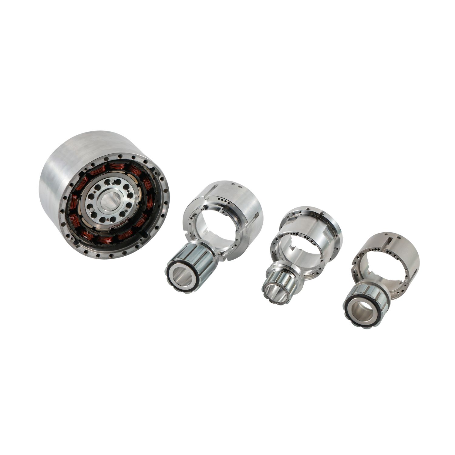
Humanoid robotics operates under a strict physics constraint. Engineers must achieve maximum degrees of freedom within tight anthropomorphic weight and space limits. Every gram impacts the center of gravity. Every millimeter dictates the kinematic envelope. Traditional housed motors and solid-shaft designs consistently fail to meet these rigorous demands. They introduce parasitic weight into the limbs and create bulky, unnatural joint profiles. Furthermore, external cable routing across moving joints creates severe vulnerabilities during complex physical maneuvers.
Modern humanoid joints require a completely different architectural standard. Hollow Frameless Motors solve these complex routing, thermal, and system integration challenges. They allow engineers to embed actuation directly into the robot's skeletal structure. This direct integration eliminates redundant components, maximizes power density, and redefines what is kinematically possible for bipedal machines.
Key Takeaways
Direct Structural Integration: Frameless architectures eliminate redundant housings and bearings, reducing overall joint mass and improving the torque-to-weight ratio.
Optimized Cable Management: Large inner diameter (hollow shaft) designs allow power, data, and encoder cables to pass directly through the center of rotation, preventing wire fatigue and enabling continuous joint rotation.
Thermal Efficiency: Integrating the stator directly into the robot's metallic joint housing utilizes the robot's chassis as a massive heat sink, superior to isolated housed motors.
Dynamic Responsiveness & Proprioception: Low rotor inertia inherent in frameless torque motors enables the rapid acceleration required for bipedal balancing, while smooth torque delivery feeds high-fidelity data to AI-driven perception models.
Table of Contents
Toggle
Core Design Requirements for Humanoid Robot Joints
Size Limits & Human‑Like Shape Requirements
Humanoid joints must fit within strict volumetric limits to mimic human biomechanics accurately. Shoulders require complex spherical motion within a compact shoulder girdle. Elbows must remain narrow to avoid colliding with the torso during arm swings. Ankles demand dual-axis pitch and roll capabilities in a space barely larger than a human heel. When engineers use oversized motors, they push the robot's center of gravity outward. This ruins bipedal balance and increases the inertial load on proximal joints.
The primary success criterion for joint actuators is achieving exceptionally high power density within a highly restricted outer diameter (OD). Engineers measure this in Newton-meters per kilogram (Nm/kg). If the actuator exceeds the target OD, the entire limb must be scaled up, adding structural mass that cascades into higher torque requirements for every other joint in the kinematic chain.
Joint Location
Typical Max OD (mm)
Primary Kinematic Challenge
Torque Requirement Profile
Shoulder Pitch/Roll
80 - 100
Avoiding torso collision during arm swing
High continuous holding torque
Elbow Pitch
60 - 75
Maintaining a slim limb profile
High speed, moderate torque
Hip Pitch/Roll
110 - 140
Supporting full upper body mass
Extreme peak torque for jumping
Ankle Pitch/Roll
70 - 90
Fitting within the heel envelope
High continuous torque for balancing
The Cable Management Bottleneck
A humanoid limb is an electrically dense environment. Three-phase power lines carry high currents to distal motors. High-resolution absolute encoders require shielded twisted-pair cables for clean position signals. Force and torque sensors demand noise-free analog pathways. EtherCAT or CAN bus communication lines must maintain continuous, microsecond-level data flow across the entire robot network.
Routing these cables externally across moving joints introduces unacceptable failure rates. Wires pinch during extreme flexion. Cables fatigue and snap after thousands of bending cycles. External routing severely limits the range of motion, often restricting joints to less than 120 degrees of travel. Internal routing is an absolute necessity for achieving 360-degree or high-angle joint rotation without cable binding. The mechanical design must provide a clear, unobstructed path through the exact center of rotation.
Dynamic Response, Bipedal Locomotion, and AI Perception
Bipedal walking is essentially a process of controlled falling. The robot requires rapid, micro-second torque adjustments to maintain dynamic balance. Low rotor inertia is non-negotiable for this rapid acceleration. High inertia rotors resist changes in velocity, causing the robot to react sluggishly to balance disturbances. Zero backlash ensures instantaneous dynamic response when reversing direction, preventing the dead-band delays that cause walking algorithms to fail.
Beyond physical movement, the motor acts as a critical sensor. Precise current feedback provides proprioceptive data. AI control systems rely on this high-fidelity torque data to understand terrain compliance, detect obstacles, and adjust posture dynamically. If the motor exhibits high friction or inconsistent torque delivery, the current draw fluctuates randomly. This injects noise into the proprioceptive data, blinding the AI to the actual physical state of the robot's interaction with the ground.
How Hollow Frameless Motors Solve Core Engineering Challenges (Solution Categories)
The "Hollow" Advantage: Through-Bore Routing and Slip Rings
The hollow aperture of these motors provides a dedicated internal pathway. Engineers use this coaxial routing for electrical cables, optical fibers, and even pneumatic lines. This internal channel protects sensitive wiring from environmental hazards, dust, moisture, and mechanical pinching. The cables twist gently along the central axis rather than bending sharply over a hinge point.
For joints requiring infinite continuous rotation, such as the torso yaw or wrist roll, engineers integrate slip rings directly within the hollow shaft. The slip ring passes power and data across the rotating interface without any physical wire connection. This completely eliminates mechanical wear on wiring harnesses. The direct result is a massive increase in the robot's mean time between failures (MTBF), transforming a fragile prototype into a robust machine capable of continuous operation.
The "Frameless" Advantage: Mass Reduction and Direct Integration
A frameless motor consists of only two active electromagnetic components. The manufacturer supplies the rotor and stator separately. There is no housing, no shaft, and no bearings. Engineers press-fit or thermally bond the stator directly into the robot's structural joint housing. They mount the rotor directly to the driven shaft or the wave generator of a harmonic drive.
This architecture eliminates redundant motor housings. It utilizes the joint's existing structural bearings, typically thin-section cross-roller bearings, to support both the joint load and the rotor alignment. The resulting weight savings drastically improve the robot's overall agility. By stripping away the dead weight of aluminum motor cans and duplicate steel bearings, engineers maximize the active electromagnetic mass within the joint.
High Torque Density in Compact Envelopes
Frameless torque motors utilize highly optimized electromagnetic designs. They feature high pole counts, often utilizing 21 or more pole pairs, that deliver maximum continuous torque at very low rotational speeds. This specific torque profile aligns perfectly with the biomechanical requirements of humanoid walking, which demands high force at relatively low RPMs.
This high torque density often eliminates the need for multi-stage, high-ratio planetary gearboxes. Removing these complex gear trains reduces mechanical complexity. It lowers the overall joint weight and reduces the axial length of the actuator. Most importantly, it minimizes back-drivability issues. A joint with a low gear ratio can be back-driven by external forces, allowing the limb to absorb impact forces naturally when the robot's foot strikes the ground.
Modular Scalability and Accelerated Iteration
Standardizing on a specific family of hollow frameless motors fundamentally accelerates robotics development cycles. Robotics teams can establish a baseline actuator architecture using a common stator diameter. They can then scale the torque output simply by changing the stack length of the motor.
Engineers can iterate rapidly on the external joint structure, chassis materials, and kinematics. They do not need to redesign the internal actuator mechanics for every minor revision. They do not have to wait months for custom motor builds. This modular approach significantly speeds up time-to-market for new humanoid iterations, allowing software teams to receive functional hardware platforms much faster.
Compare Hollow Frameless Motors With Conventional Actuators
Hollow Frameless Motors vs. Housed BLDC Motors
The integration footprint heavily favors frameless architectures. Frameless motors offer superior volumetric efficiency because every millimeter of space is dedicated to electromagnetic material. Housed motors introduce parasitic volume through their external casings, end bells, and redundant bearings. When space is measured in millimeters, housed motors simply consume too much room.
Thermal pathways also differ significantly. Frameless motors conduct heat directly into the robot's metal chassis, utilizing the entire limb as a heat sink. Housed motors trap heat inside their insulated casings. The air gap between the motor casing and the robot's structure acts as a thermal barrier, leading to rapid thermal throttling under heavy loads. However, frameless motors do require precision alignment by the integrator, whereas housed motors offer simpler plug-and-play assembly.
Actuator Type
Volumetric Efficiency
Thermal Management
System Weight
Assembly Complexity
Hollow Frameless Motor
Excellent (No parasitic housing)
Direct conduction to chassis
Low (Shared structural components)
High (Requires precision GD&T)
Housed BLDC Motor
Poor (Redundant casing/bearings)
Trapped heat within casing
Moderate to High
Low (Plug-and-play)
Hydraulic Actuator
Good (At the joint level)
Fluid cooling required
Very High (Pumps, lines, valves)
High (Plumbing and sealing)
Hollow Frameless Motors vs. Hydraulic/Pneumatic Actuators
Legacy humanoid designs often utilized hydraulics to achieve high power density. While powerful, hydraulic systems introduce immense system-level weight. Hydraulic pumps, pressurized fluid lines, accumulators, and servo valves add significant mass to the robot's torso. This high center of gravity makes dynamic balancing exceptionally difficult.
Electric frameless motors combined with modern high-discharge lithium batteries weigh substantially less. Furthermore, solid-state electrical reliability far exceeds the maintenance demands of fluid systems. Electric motors eliminate catastrophic leakage risks, operate with vastly superior control precision, and generate a fraction of the acoustic noise. Pneumatic systems suffer from air compressibility, making precise position control nearly impossible for rigid bipedal walking.
Creating Highly Integrated Actuator Modules
Hollow frameless motors serve as the foundational core for highly integrated system layouts. Engineers rarely use these motors in isolation. They combine the frameless motor, a strain wave gear (harmonic drive), and dual position encoders into a single assembly. The absolute encoder tracks the joint output position, while the incremental encoder tracks the motor rotor position.
By nesting these components coaxially, engineers create an ultra-compact robotic joint module. The rotor mounts directly to the wave generator plug of the harmonic drive. The stator sits concentrically around it. The encoders mount directly to the rear of the assembly. This synergy maximizes torque output while keeping the axial length of the joint incredibly short, allowing it to fit within the tight confines of a humanoid knee or elbow.
Application of Coreless Motors in Humanoid Robots
It is critical to map specific motor types to their optimal use cases within a single humanoid architecture. Hollow frameless torque motors are engineered for high-torque, load-bearing joints. Engineers deploy them in the hips, knees, ankles, and shoulders where moving the robot's mass is the primary objective.
Conversely, coreless motors lack an iron core in the rotor. They offer extremely low inertia and high speeds but lower overall torque. Engineers utilize coreless motors for lightweight, highly dynamic applications, such as actuating the individual articulated fingers of a humanoid hand. Understanding this distinction prevents engineers from over-specifying heavy torque motors for delicate end-effector tasks.
Critical Technical Parameters for Motor Selectio
Continuous vs. Peak Torque Ratings
Evaluating torque requirements demands a precise understanding of the joint's specific load profile. Holding a static posture, such as a deep squat or carrying a heavy payload, relies entirely on the motor's continuous torque rating. This is the maximum torque the motor can generate indefinitely without exceeding its thermal limits.
Executing explosive movements, like jumping or recovering from a trip, relies on peak torque. Engineers must analyze the motor's thermal time constant. This metric dictates exactly how long the motor can sustain peak torque before the copper windings overheat and suffer catastrophic insulation failure. Relying too heavily on peak torque for sustained operations will result in rapid motor burnout.
Thermal Dissipation and Stator Design
Heat generation is the primary limiting factor in humanoid joint performance. Winding density and copper fill factor directly influence how much heat the stator generates under load. A higher fill factor reduces electrical resistance, thereby reducing I⊃2;R copper losses and heat generation.
Engineers cannot evaluate a motor's continuous torque rating in a vacuum. They must calculate it based on the specific heat-sinking capacity of the robot's joint material. The material chosen for the joint housing dictates how effectively heat moves away from the stator.
Acts as an insulator; requires active cooling or thermal potting.
Cogging Torque, Smoothness, and Force Feedback
Low cogging torque is absolutely critical for advanced humanoid control. Cogging torque is the magnetic attraction between the rotor magnets and the stator teeth when the motor is unpowered. High cogging torque introduces mechanical stuttering at low speeds. This ruins force-feedback mechanisms, disrupts impedance control, and makes human-robot physical interaction unsafe.
Engineers must look for specific stator and rotor design features to minimize torque ripple. Skewed magnets and fractional slot windings are highly effective at smoothing torque delivery. This smooth operation directly improves the quality of proprioceptive current data fed into the robot's behavioral and decision-making algorithms. Clean current data allows the robot to "feel" the ground accurately.
Aperture Size vs. Overall Outer Diameter (OD)
Selecting the right motor involves a strict mathematical trade-off. Maximizing the hollow inner diameter (ID) provides ample room for thick wiring harnesses, pneumatic tubes, and slip rings. However, increasing the ID while maintaining a strict outer diameter (OD) leaves less physical radial space for electromagnetic material.
Less space for copper and magnets directly reduces the motor's torque generation capabilities. Engineers must calculate the absolute minimum cable clearance required for the specific joint. They must then select a motor that provides that exact ID while maximizing the remaining OD for torque production. Over-sizing the hollow bore unnecessarily sacrifices critical joint strength.
Practical Integration Issues and Risk Countermeasures
Bearing Alignment and Air Gap Tolerances
Frameless motors shift the burden of mechanical alignment onto the robotics integrator. The engineer must establish and maintain the precise air gap between the rotor and stator. This gap is often less than 0.5mm. Misalignment causes uneven magnetic pull. This leads to severe efficiency losses, excessive heat generation, or catastrophic mechanical failure where the rotor strikes the stator during high-load deflection.
Engineers mitigate this risk through strict manufacturing and assembly protocols:
Machine the joint housing inner diameter to a precise H7 tolerance to ensure a perfect stator fit.
Apply a thermally conductive retaining compound to the stator outer diameter before insertion.
Heat the aluminum housing to 120°C to expand the bore, allowing the stator to drop in without galling.
Verify concentricity and perpendicularity using a dial indicator before attempting rotor insertion.
Utilize specialized guide jigs to lower the highly magnetic rotor into the stator without it snapping to the side.
Commutation and Encoder Integration Challenges
Because frameless motors lack a factory-aligned housing, commutation alignment falls entirely on the integration team. The engineer must perfectly align the rotor's magnetic poles with the position encoder to ensure smooth startup and optimal torque delivery. Without this alignment, the motor will stall, draw massive current, or spin unpredictably upon power-up.
Engineers mitigate this challenge through specific electrical integration steps:
Mount an absolute encoder (such as BiSS-C or EnDat protocols) rigidly to the joint housing.
Secure the robot limb in a rigid test stand to prevent unexpected movement during calibration.
Initiate the servo drive's automated phase-finding algorithm to lock the rotor to a known magnetic pole.
Record the electrical angle offset in the drive's non-volatile memory.
Integrate Hall effect sensors directly into the stator to provide reliable, hardware-level commutation data as a failsafe.
Supply Chain and Customization Trade-offs
Off-the-shelf frameless motors rarely match the highly specific ID and OD requirements of a custom humanoid joint perfectly. Forcing a standard motor into a custom joint often compromises the robot's kinematics, forcing the limb to be wider or longer than desired. However, commissioning a completely custom motor introduces massive Non-Recurring Engineering (NRE) costs and lead times exceeding six months.
Engineers mitigate this by selecting motor manufacturers that offer scalable modular platforms. Look for suppliers capable of providing rapid winding customizations to adjust the voltage constant (Kv). Seek out platforms that allow for slight stack length adjustments without requiring a full ground-up redesign of the stator laminations. This balances custom performance with off-the-shelf lead times.
Conclusion
Download exact 3D step files from the manufacturer to perform rigorous spatial fit-checks and verify internal cable clearances against your existing wiring harness diameter.
Calculate the required thermal dissipation area on your joint housing to ensure it meets the motor's continuous torque thermal limits based on your specific chassis material.
Order a prototype stator and rotor set to physically validate your press-fit tooling, thermal bonding compounds, and air-gap alignment jigs.
Run a commutation phasing test with your selected absolute encoder and servo drive to confirm electrical compatibility and zero commutation error.
FAQ
Q: What is a hollow frameless motor?
A: A hollow frameless motor is an electric actuator supplied as a separate rotor and stator pair without a shaft, bearings, or external housing. It features a large central bore, allowing engineers to integrate the electromagnetic components directly into a machine's structural mechanics.
Q: Why is a hollow shaft critical for humanoid robots?
A: The hollow shaft allows engineers to route power, data, and sensor cables directly through the center of the joint. This internal routing prevents cable fatigue, enables highly integrated system layouts, and allows for infinite, 360-degree joint rotation without wire pinching.
Q: How do you cool a frameless motor in a robotic joint?
A: Frameless motors rely on conductive cooling. The stator is press-fit or thermally bonded directly into the robot's thermally conductive metal chassis. This transforms the entire robotic limb into a massive heat sink, dissipating heat much faster than insulated housed motors.
Q: What is the difference between frameless and housed motors?
A: Housed motors are fully self-contained units with their own external casing, internal bearings, and output shaft. Frameless motors consist only of the bare rotor and stator, relying entirely on the robot's existing structural bearings and shaft for support and alignment.
Q: How does frameless motor integration affect manufacturing speed?
A: While the requirement for high-precision CNC machining and alignment increases initial assembly complexity, the modular nature of frameless motors significantly accelerates overall robot development. It allows teams to iterate on joint mechanics without waiting for custom motor redesigns.
Q: Can hollow frameless motors be used with harmonic drives?
A: Yes. Hollow frameless motors are frequently paired with harmonic drives. The rotor is typically mounted directly to the wave generator of the harmonic drive, creating an ultra-compact, high-torque, zero-backlash joint module ideal for humanoid robotics.