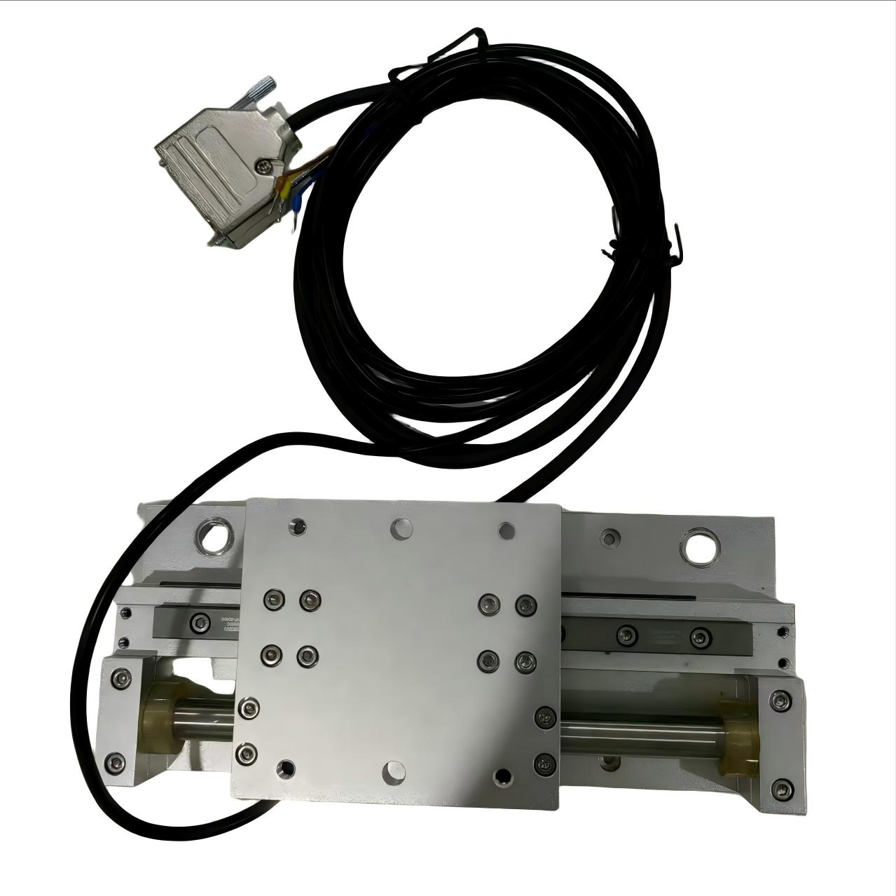
Transitioning from rotary-to-linear mechanical transmissions, like ball screws or rack-and-pinion assemblies, to direct drive systems is mandatory for achieving sub-micron accuracy. Selecting the right motor dictates the success or failure of the entire motion system. Over-specifying a motor inflates the system footprint and adds unnecessary mass. Under-specifying leads to thermal failure, unacceptable settling times, or compromised trajectory tracking due to cogging forces and structural resonance.
This guide provides a systematic framework for evaluating, sizing, and selecting a Linear Motor For Precision Positioning. We balance dynamic performance requirements with thermal, environmental, and control constraints to ensure optimal machine design. You will learn how to match electromagnetic topologies to your kinematic profile, mitigate integration risks, and optimize servo control for nanometer-level tracking.
Topology Dictates Precision: Ironless linear motors eliminate cogging for nanometer-level tracking, while ironcore motors provide the high force density required for heavy payloads.
Thermal Management is Critical: Continuous force capabilities are strictly limited by the system's ability to dissipate heat; thermal expansion directly degrades positioning accuracy at the metrology level.
System-Level Approach Required: A high-end linear motor cannot achieve precision positioning without an equally capable high-resolution encoder, rigid structural base, and advanced servo drive with high-frequency update rates.
Table of Contents
Toggle
Linear Motor Types: Pick the Right Motor for Your Use Case
Matching the motor's electromagnetic design to the application requires a deep understanding of payload dynamics, speed profiles, environmental conditions, and smoothness requirements. The topology you choose fundamentally limits the maximum achievable performance of the system. Engineers must evaluate the trade-offs between force density, thermal dissipation, and velocity ripple.
Topology
Force Density
Cogging
Heat Dissipation
Best Application
Ironless (U-Channel)
Low
Zero
Poor
Semiconductor inspection, optical metrology
Ironcore (Flat)
High
High
Excellent
Machine tools, heavy payload gantries
Slotless
Medium
Low
Good
Digital printing, medical imaging
Tubular (Shaft)
Medium
Zero (Radial)
Good
Packaging, assembly automation
U-Channel Ironless Linear Motors
Ironless motors feature a forcer constructed of copper coils encapsulated in epoxy. These coils move between dual parallel magnet tracks arranged in a U-channel configuration. Because there is no iron in the forcer, there is absolutely no magnetic attractive force between the forcer and the magnet way. The coil winding techniques often utilize overlapping patterns to maximize the volume of copper within the magnetic field, compensating slightly for the lack of an iron core.
This design yields zero cogging. The absence of iron eliminates the magnetic detent forces that typically cause velocity ripple. The moving mass remains exceptionally low, allowing for extreme acceleration rates. Bearings experience zero magnetic pre-load, which reduces friction and extends the life of the linear guides. The lack of attractive force also simplifies the mechanical design of the machine base, as it does not need to resist massive downward pulls.
These characteristics make ironless topologies the standard for ultra-high precision positioning. They excel in constant velocity scanning applications, such as semiconductor wafer inspection, flat panel display manufacturing, and optical metrology. Highly dynamic, light-payload moves benefit immensely from the high force-to-mass ratio. When paired with an air bearing system, an ironless motor can achieve tracking errors measured in single-digit nanometers.
However, this topology presents distinct trade-offs. The continuous force density is significantly lower compared to ironcore alternatives. Thermal dissipation is inherently poor because the heat-generating coils are insulated by epoxy rather than mounted directly to a thermally conductive iron stator. Heat must dissipate through the air gap or be actively managed via forced air or liquid cooling plates attached to the forcer mounting surface. The thermal time constant is very short, meaning the coils can overheat rapidly during aggressive acceleration profiles if not properly sized.
Flat Ironcore Linear Motor
Ironcore motors utilize coils wound around silicon steel laminations. This iron-based forcer interacts with a single, flat permanent magnet track. The presence of the iron core concentrates the magnetic flux, resulting in a highly efficient electromagnetic circuit. Manufacturers often employ fractional slot windings to optimize the flux linkage and maximize the force output per amp of current.
This design generates massive continuous and peak forces. The iron core acts as an excellent thermal conductor, transferring heat away from the coils and into the machine base or an integrated liquid cooling channel. Force density is maximized, allowing compact motors to drive massive loads. The robust construction can withstand harsh industrial environments better than exposed epoxy coils.
Ironcore topologies dominate high-acceleration point-to-point moves. They are the preferred choice for heavy payloads, CNC machining centers, and large-format laser cutting gantries where overcoming inertia is the primary engineering challenge. They provide the brute force necessary to accelerate heavy steel carriages and cutting heads at multiple Gs.
The primary drawback is the introduction of cogging forces. As the iron teeth of the forcer pass over the alternating poles of the magnet track, magnetic attraction fluctuates. This creates a torque ripple equivalent that complicates sub-micron settling and introduces velocity errors during slow-speed scanning. To mitigate this, manufacturers often skew the magnets on the track, which smooths the transition between poles but slightly reduces overall force. Furthermore, the strong magnetic attraction between the forcer and the track requires heavy-duty linear guides to maintain the air gap and prevent structural deflection.
Slotless Linear Motors
Slotless designs attempt to bridge the gap between ironless and ironcore technologies. The coils are mounted to an iron back-plate, but the design lacks the traditional slotted teeth found in standard ironcore stators. The coils sit in the air gap between the back-iron and the magnets. The manufacturing process for these coils is highly specialized, often requiring them to be formed and bonded directly to the back-iron under high pressure.
This configuration significantly reduces cogging compared to slotted ironcore designs. The continuous magnetic attraction is lower, and the transition between magnetic poles is smoother. Simultaneously, the back-iron provides better heat dissipation and higher force density than a purely ironless design. The magnetic flux is balanced more evenly across the coil surface, reducing localized hot spots.
Slotless motors fit applications requiring a middle ground between extreme smoothness and high force. High-end digital printing, DNA sequencing machines, and precision assembly automation frequently utilize this topology to balance velocity stability with payload capacity. They offer a practical compromise when an ironless motor lacks the necessary thrust, but an ironcore motor introduces too much vibration.
The trade-offs include a heavier moving mass than ironless designs. The system still exhibits some magnetic attraction to the track, requiring robust bearing support, though less extreme than fully slotted ironcore motors. The air gap in a slotless motor is typically larger to accommodate the coils, which requires stronger, more expensive rare-earth magnets to maintain flux density.
Tubular (Shaft) Linear Motors
Tubular motors utilize a cylindrical design. The forcer, containing the coils, moves along a magnetic rod or shaft. The magnetic flux is distributed radially, creating a highly efficient and symmetrical force profile. The internal magnet arrangement often utilizes a Halbach array, which concentrates the magnetic field on the exterior of the shaft while canceling it out on the interior, maximizing efficiency.
The symmetrical force distribution eliminates radial attractive forces on the bearings. The form factor closely mimics pneumatic cylinders, making them an easy drop-in replacement for upgrading legacy automation equipment to direct drive servo control. The enclosed nature of the shaft makes it easier to achieve high IP ratings for washdown environments.
Packaging, food processing lines, and moderate-precision positioning systems benefit from this compact footprint. They excel in environments where space is heavily constrained and multi-axis integration is required. The lack of an exposed flat magnet track reduces the risk of ferrous debris contamination.
However, tubular designs are less scalable for extreme precision compared to flat ironless designs. Stroke lengths are strictly limited by shaft deflection. As the shaft gets longer, it sags under its own weight or deflects under dynamic loads, altering the critical air gap and degrading performance. Supporting the shaft at both ends mitigates this, but limits the travel of the forcer.
Performance Standards: Motor Sizing & Specification Selection
Translating kinematic requirements into electromechanical specifications is the core of the sizing process. A Linear Motor must be mathematically validated against the specific motion profile before selection. Guesswork during this phase leads to catastrophic mechanical failures or severe performance bottlenecks.
Parameter
Formula / Concept
Engineering Significance
Peak Force (Fp)
Fp = (m * a) + F_friction + F_external
Determines the maximum current the drive must supply during acceleration.
Dictates the continuous thermal load on the motor coils. Must be lower than the motor's continuous force rating.
Back-EMF (Vbemf)
Vbemf = Ke * v
Limits the maximum achievable velocity based on the available bus voltage from the servo drive.
Force Requirements: Continuous (Fc) vs. Peak (Fp)
Begin by calculating the total moving mass. This includes the mass of the motor forcer, the payload, the moving portion of the linear bearings, the encoder readhead, and the dynamic weight of the cable management system. Underestimating the cable track mass is a frequent cause of sizing errors in long-stroke applications. You must also account for the mass of any tooling or fixtures attached to the carriage.
Next, determine the Peak Force required for maximum acceleration. Use the fundamental equation of motion: Force equals mass times acceleration, plus friction, plus any opposing external forces. Peak force is typically required only during the acceleration and deceleration phases of the motion profile. Ensure the motor's peak force rating exceeds this calculated value with a safety margin of at least 20%. If the peak force requirement exceeds the motor's capability, the servo drive will saturate, and the carriage will fail to follow the commanded trajectory.
Finally, calculate the Root Mean Square (RMS) force over the complete motion profile. The RMS calculation accounts for the force required during acceleration, constant velocity, deceleration, and the dwell time between moves. The dwell time is critical; a longer dwell time allows the motor to cool, lowering the overall RMS value. The RMS force dictates the required Continuous Force rating of the motor. If the calculated RMS force exceeds the motor's continuous force rating, the coils will overheat, degrading the insulation and eventually causing a short circuit.
Define the complete motion profile, including acceleration time, constant velocity time, deceleration time, and dwell time.
Calculate the total moving mass, factoring in all dynamic components like cables and brackets.
Determine the peak force required to achieve the target acceleration rate.
Calculate the RMS force to establish the continuous thermal load on the motor coils.
Apply a 20% safety margin to both peak and continuous force calculations to account for unexpected friction or payload variations.
Precision, Accuracy, and Repeatability
It is critical to differentiate between motor capabilities and encoder limitations. A direct drive motor has infinite theoretical resolution; it simply moves where the magnetic field commands it. The actual positioning precision is dictated entirely by the feedback device and the mechanical rigidity of the system. The motor is merely the muscle; the encoder is the nervous system.
The linear encoder resolution determines the minimum incremental move. Optical encoders provide the highest resolution and lowest interpolation errors, making them ideal for sub-micron tasks. They utilize a glass or steel scale with finely etched lines, read by an optical sensor. Magnetic encoders offer superior robustness in dirty environments but generally provide lower absolute accuracy. The encoder resolution must be significantly finer than the target positioning tolerance to allow the servo loop to maintain stability. If the resolution is too coarse, the motor will hunt for position, causing high-frequency vibration.
Abbe errors play a massive role in system accuracy. An Abbe error occurs when the measurement axis (the encoder scale) is offset from the working point of interest (the payload or tool center point). Any angular deflection in the bearings (pitch, yaw, or roll) multiplies over this offset distance, creating a linear positioning error. Always mount the encoder scale as close to the point of interest as physically possible. Furthermore, consider the thermal expansion coefficient of the scale material. A steel tape scale will expand differently than a glass scale when subjected to temperature variations, directly impacting absolute accuracy.
Kinematics: Velocity, Acceleration, and Settling Time
Evaluate the back-EMF constant (Ke) of the motor. As the motor moves through the magnetic field, it generates a voltage that opposes the drive voltage. To reach the target maximum velocity, the servo drive's bus voltage must be significantly higher than the generated back-EMF. If the back-EMF equals the bus voltage, the motor cannot draw current, and acceleration drops to zero. Always verify that the drive's DC bus voltage is sufficient for the application's top speed.
Analyze the force-to-mass ratio for high-frequency, short-stroke applications. In these scenarios, the motor spends its entire duty cycle accelerating and decelerating. Minimizing the moving mass of the forcer and payload is more effective than selecting a larger, heavier motor with higher force. Consider implementing S-curve motion profiles to limit jerk (the derivative of acceleration). High jerk values excite mechanical resonances and cause severe machine vibration, which degrades surface finish in machining applications and increases settling time.
Minimizing settling time requires stiff mechanical coupling and advanced feed-forward control algorithms. The time it takes for the payload to enter and remain within the target position window directly impacts machine throughput. Structural resonances in the machine base or payload bracket will prolong settling time, regardless of the motor's capabilities. A highly rigid structure pushes resonant frequencies higher, allowing the servo drive to be tuned more aggressively without becoming unstable.
Control Architecture and Servo Tuning
Direct drive systems demand high-bandwidth servo drives. Because there is no mechanical reduction (like a gearbox or ball screw) to dampen load disturbances, the servo drive must react instantaneously to positional errors. Industrial Ethernet protocols like EtherCAT or PROFINET IRT are necessary to handle the rapid current loop and position loop update rates required. The current loop bandwidth should ideally exceed 2 kHz to ensure the drive can inject current fast enough to counter dynamic disturbances.
Utilize Bode plots during the commissioning phase to identify mechanical resonances. A Bode plot maps the system's frequency response, revealing structural weaknesses that limit servo gains. Once identified, these resonant frequencies can be suppressed using notch filters or low-pass filters within the servo drive. Implementing velocity feed-forward and acceleration feed-forward parameters allows the drive to anticipate the required current based on the motion profile, drastically reducing following errors and enabling faster settling times.
System Integration and Implementation Risks
Addressing the physical realities of integrating a motor into a machine chassis is where theoretical designs often fail. Risk mitigation at the mechanical level is mandatory. A perfectly sized motor will still fail if the mechanical integration is flawed.
Thermal Management and Heat Dissipation
Current flowing through the motor coils generates heat due to electrical resistance. Excessive heat causes thermal expansion in the machine base. If the base expands, the encoder scale shifts, destroying positioning accuracy at the metrology level. A temperature rise of just a few degrees can cause micrometers of expansion in standard aluminum or steel structures. Most motors include embedded PTC or NTC thermistors to monitor coil temperature, allowing the drive to trigger a fault before the insulation melts.
Mitigate this risk by sizing the motor for a lower thermal rise, effectively running a larger motor at a fraction of its capacity. For ironcore motors, utilize integrated water cooling channels to extract heat before it reaches the machine frame. Forced air cooling can also be applied, though it introduces turbulence that may disturb ultra-precision air bearings. In ultra-precision applications, isolate the motor thermally from the metrology frame using zero-expansion materials like Invar, ensuring the measurement loop remains dimensionally stable regardless of motor temperature.
Bearing Selection and Air Gap Maintenance
Linear motors provide driving force but offer zero structural support. The linear guides must carry the payload, resist external machining forces, and maintain a precise air gap between the forcer and the magnet track. Misalignment causes mechanical binding, while structural deflection alters the magnetic flux density, degrading force output and efficiency. The air gap is typically less than 1mm; any variation directly impacts the motor's Ke and Kt constants.
Select recirculating ball or roller guides for ironcore motors. These bearings are pre-loaded to handle the massive, continuous magnetic attraction forces pulling the forcer toward the track. Heavy preload classes increase rigidity but also increase friction, which must be factored into the sizing calculations. For ironless motors, where magnetic attraction is zero, cross-roller bearings or air bearings are preferred to maximize smoothness and minimize friction. Machine all mounting surfaces to strict flatness and parallelism tolerances to prevent bearing bind and air gap variation. Establish a strict lubrication schedule for the linear guides to prevent premature wear.
Cable Management (The Hidden Failure Point)
Moving cables introduce parasitic drag, limit precision, and represent the primary cause of hardware failure in direct drive systems. As the cable track bends and flexes, it transmits variable forces into the moving carriage, disturbing the servo loop and increasing settling time. A poorly designed cable track acts like an unpredictable spring attached to the payload.
Specify high-flex cables with polyurethane jackets designed for millions of bending cycles.
Maintain a minimum bend radius of at least 10 to 15 times the outer diameter of the thickest cable in the track.
Physically separate power cables from high-resolution encoder cables using dividers within the cable track to prevent electromagnetic interference.
Anchor cables securely at both the moving carriage and the stationary base using dedicated strain relief combs.
Environmental Protection and Safety Mechanisms
Permanent magnets act as powerful traps for ferrous debris. In machining environments, metal chips attracted to the magnet track can easily wedge into the air gap, destroying the motor coils instantly. Power loss in vertical applications presents a severe safety hazard; without the mechanical friction of a ball screw, the payload will plummet due to gravity.
Specify IP65+ rated enclosed linear motors or utilize non-magnetic stainless steel magnet covers for dirty environments. Implement positive air pressure inside bellows to keep contaminants out. Equip linear guides with heavy-duty wiper seals. For vertical Z-axis applications, integrate fail-safe pneumatic or electromagnetic linear brakes that engage immediately upon power loss. Employ counterbalance systems, such as pneumatic cylinders or magnetic springs, to offset the static weight of the payload, reducing the continuous force burden on the motor and preventing catastrophic crashes.
Controller and Drive Compatibility
The servo drive acts as the brain of the direct drive system. Hardware compatibility between the motor, encoder, and drive is non-negotiable for precision positioning. The drive must translate the high-resolution encoder signals into precise current vectors applied to the motor coils.
Ensure the selected servo drive can handle the high commutation frequencies required by high-speed linear motors. As the motor moves rapidly across the magnetic poles, the drive must switch the current between the coil phases at an exceptionally high rate. If the drive's processor cannot keep up with the commutation frequency, the motor will experience torque ripple, excessive heating, or a complete loss of synchronization. Verify the drive's PWM (Pulse Width Modulation) switching frequency is high enough to maintain a smooth current waveform.
Evaluate the availability of advanced control features within the drive's firmware. Cogging compensation algorithms map the magnetic detent forces of ironcore motors during a learning phase and inject opposing current to cancel out the ripple, artificially smoothing the motion. For wide gantry systems utilizing dual-drive axes, the controller must support strict gantry synchronization to prevent mechanical racking and binding during high-acceleration moves.
Absolute Encoders: Provide immediate position data upon power-up, allowing the drive to commutate the motor instantly without any physical movement.
Wake-and-Shake: The drive injects a small, high-frequency current pulse into the coils to determine the magnetic pole position. This causes a slight vibration in the carriage.
Hall Effect Sensors: Discrete sensors embedded in the motor coils detect the magnetic field polarity, providing coarse commutation data until the incremental encoder finds its index mark.
Conclusion
Compile your exact moving mass, stroke length, and motion profile data to calculate the required RMS and peak forces.
Filter your topology choices based on acceptable cogging limits and the system's capacity for thermal dissipation.
Select a high-resolution encoder and rigid bearing system that physically supports your target positioning tolerance.
Utilize manufacturer sizing software to validate thermal, structural, and control loop assumptions before purchasing hardware.
FAQ
Q: What is the difference between accuracy and repeatability in a linear motor?
A: Accuracy is how closely the motor reaches a commanded absolute position. This depends on encoder quality, thermal stability, and mechanical alignment. Repeatability is the system's ability to return to the exact same position over multiple cycles. Repeatability is generally much tighter than accuracy and depends on system friction, bearing quality, and servo tuning.
Q: Why do ironcore linear motors experience cogging?
A: Cogging is caused by the magnetic attraction between the iron teeth of the forcer and the permanent magnets on the track. As the forcer moves, the iron teeth align and misalign with the alternating magnetic poles. This creates a fluctuating attractive force that manifests as a physical ripple or stutter in the motion profile.
Q: Can a linear motor operate in a cleanroom or vacuum environment?
A: Yes. Linear motors are ideal for cleanrooms because they lack contacting moving parts, meaning they do not generate wear particles or require lubrication. Vacuum applications require specialized motors built with low-outgassing materials and advanced thermal management strategies, as standard convection cooling is impossible in a vacuum.
Q: How do I manage the magnetic attraction forces in an ironcore linear motor?
A: The machine base and linear guide bearings must be specifically sized to handle the continuous attractive force, which can easily reach thousands of Newtons. High-load recirculating roller bearings are typically used. The structure must be rigid enough to prevent deflection, ensuring the critical air gap between the forcer and magnet track remains perfectly constant.
Q: What type of encoder is required for a linear motor?
A: Precision positioning typically requires optical or high-end magnetic linear encoders. The encoder provides the position feedback the servo drive needs to control the motor. As a general engineering rule, the encoder resolution must be 5 to 10 times finer than the application's required positioning tolerance to maintain servo stability.
Q: How does back-EMF limit linear motor speed?
A: As the motor coils move through the magnetic field, they generate a voltage called back-Electromotive Force (back-EMF) that opposes the voltage supplied by the servo drive. Maximum velocity is reached when the generated back-EMF equals the available bus voltage. At this point, no additional voltage is available to push current into the coils for further acceleration.
Q: Are linear motors safe for vertical (Z-axis) applications?
A: Yes, but they require mandatory additional safety mechanisms. Because direct drive systems lack the inherent mechanical friction of a ball screw or gear train, a loss of power will cause the payload to drop immediately due to gravity. Counterbalances and fail-safe linear brakes must be integrated into the mechanical design to prevent catastrophic crashes.