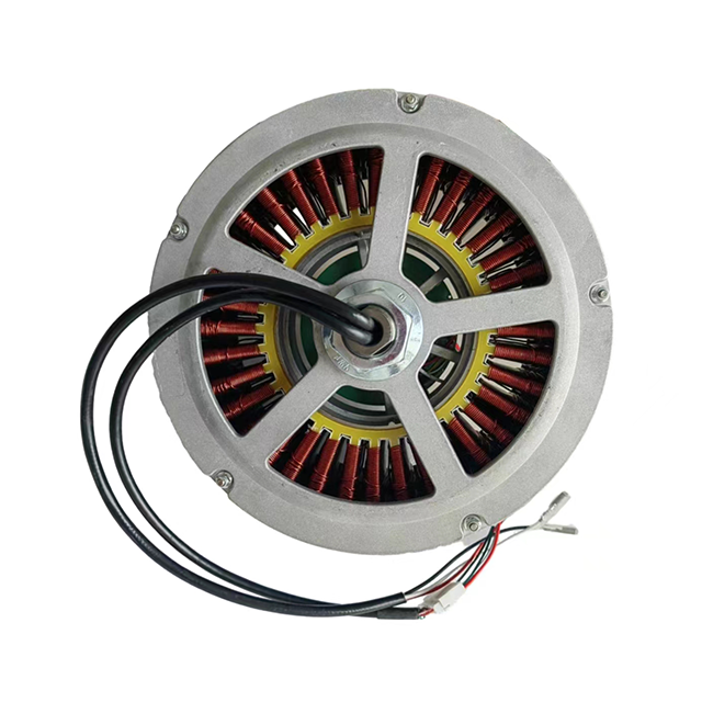
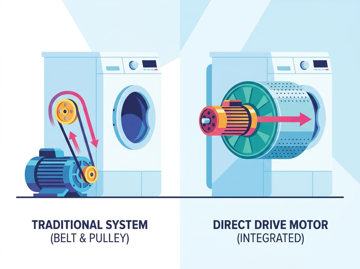
Modern industrial automation, semiconductor fabrication, and high-precision manufacturing demand sub-micron precision, higher throughput, and reduced downtime. Traditional mechanical power transmission systems rely heavily on gearboxes, belts, and pulleys. These components inherently introduce backlash, mechanical compliance, friction, and hysteresis into the motion profile. Over time, mechanical wear degrades positioning accuracy, while ongoing maintenance requirements cap system performance and limit operational efficiency on the factory floor.
The Direct Drive Motor serves as the definitive engineering solution for eliminating mechanical transmission components entirely. By directly coupling the payload to the motor structure, these systems offer unparalleled dynamic stiffness and immediate torque transfer. Specifying a direct drive system requires a rigorous evaluation of torque density, thermal management, integration complexity, and control system capabilities to ensure the machine frame can handle the unmitigated dynamic forces.
A direct drive motor couples the load directly to the motor rotor or forcer, eliminating gearboxes, couplings, and belts to achieve zero backlash and exceptional dynamic stiffness.
Successful implementation requires strict attention to thermal management and mechanical installation tolerances, as the motor absorbs load forces and thermal energy directly without the isolation of a gearbox.
High-resolution encoders and advanced servo drives with high control loop bandwidths are mandatory to manage the stiff dynamics and suppress torque ripple in direct drive systems.
Table of Contents
Toggle
How Does a Direct Drive Motor Work?
The Gearless Architecture and Electromagnetic Principles
A direct drive motor operates by mounting the load directly to the moving part of the motor assembly. In rotary systems, the payload bolts to the rotor. In linear systems, it attaches to the forcer. This gearless architecture eliminates mechanical compliance, commonly known as wind-up. Removing wind-up translates into immediate torque delivery, exceptionally high torsional stiffness, and infinite theoretical positioning resolution limited only by the feedback device.
These motors utilize permanent magnet synchronous motor (PMSM) technology. Engineers deploy high-pole-count designs, often ranging from 12 to 64 or more magnetic poles, to maximize torque density at low rotational speeds. Stator designs vary between slotted and slotless configurations. Slotted stators provide higher torque density because the iron teeth channel the magnetic flux directly toward the magnets, but they are prone to cogging. Slotless stators remove the iron teeth, offering zero cogging and ultra-smooth motion, though they deliver lower peak torque due to the larger effective air gap.
Rotary Direct Drive Motor Topologies
Frameless, or kit, motors consist of a bare stator and rotor purchased as separate components. Machine builders integrate them directly into the machine structure. This offers highly compact integration and reduces overall machine weight. However, it requires careful management of bearing alignment and air gap tolerances during assembly. Housed and cartridge motors provide fully enclosed designs with integrated bearings and feedback devices. They offer easier drop-in installation compared to the strict integration demands of frameless kits.
Configurations also differ between inner-rotor and outer-rotor designs. Inner-rotor designs optimize acceleration due to lower rotor inertia, making them suitable for highly dynamic indexing tasks. Outer-rotor designs maximize continuous torque output by providing a larger air-gap radius for a given outer diameter, which is ideal for heavy payload rotation.
Linear Direct Drive Motor Topologies
Ironcore linear motors feature copper windings wrapped around iron laminations that run over a single-sided magnet track. They generate massive force density, making them suitable for high-force pressing, heavy machining, and long-travel positioning stages. The trade-off involves managing magnetic cogging and strong attractive forces between the forcer and the magnet track, which requires heavy-duty linear guide rails.
Ironless, or U-channel, linear motors consist of an epoxy-potted coil assembly moving within a U-shaped magnet track. The complete absence of iron in the forcer eliminates attractive forces and cogging entirely. This makes ironless motors ideal for high-speed scanning, semiconductor metrology, and applications requiring extreme velocity smoothness and zero force ripple.
Direct Drive Motor vs Geared Motor: Key Differences
Performance Metric
Direct Drive Motor
Traditional Geared Servo Motor
Backlash & Hysteresis
Zero inherent backlash
Variable (arcminutes to degrees of play)
Torsional Stiffness
Extremely high; direct mechanical coupling
Limited by shaft wind-up, belt stretch, and tooth deflection
Maximum System Velocity
High (limited only by voltage bus and encoder frequency)
Limited by gearbox input speed limits
Torque at Low Speeds
Exceptional; full continuous torque available at stall
High via mechanical multiplication, but limited by gearbox thermal dissipation
System Efficiency
High (90%–95+%); no mechanical conversion losses
Lower (70%–85%) due to sliding friction and viscous shearing in gearbox
Operating Wear & Lifetime
Non-contact electromagnetic operation; lifetime limited only by bearings
Wear-prone; limited by gear tooth wear, seal degradation, and lubrication breakdown
Backlash, Hysteresis, and Positioning Accuracy
Traditional geared systems, including planetary, harmonic, and worm gears, exhibit inherent mechanical slop. Even precision zero-backlash gearboxes develop play over time as the gear teeth wear down. In contrast, a Direct Drive Motor provides a rigid, zero-backlash coupling. This elimination of lost motion significantly improves bi-directional repeatability and reduces settling times during micro-positioning steps, allowing machines to hit target positions instantly without hunting.
Dynamic Response, Acceleration, and Bandwidth
Direct drive motors deliver high torque at low speeds, or even at a complete stall, without overheating the windings. Geared motors rely on high rotational speeds and high gear reduction ratios to achieve equivalent torque at the output shaft. The rigid mechanical connection of a direct drive system allows for superior control loop bandwidth. Systems typically exceed 100 Hz in velocity bandwidth compared to less than 20 Hz for geared systems. This permits highly aggressive acceleration and deceleration profiles without exciting mechanical resonances.
Maintenance, Wear, and Lifecycle Reliability
Traditional systems face multiple failure points such as lubrication breakdown, gear tooth wear, belt stretching, and seal degradation. Direct drive motors operate via non-contact electromagnetic principles, relying only on machine-integrated or internal bearings for physical support. This drastically reduces Mean Time Between Failures (MTBF) and minimizes particle generation, making them the standard choice for cleanroom environments and vacuum chambers.
Key Factors When Choosing a Direct Drive Motor
Continuous vs. Peak Torque Requirements
Calculating RMS (Root Mean Square) torque over a highly dynamic duty cycle is critical for proper sizing. Engineers must analyze acceleration, cruise, deceleration, and dwell times accurately. Undersizing continuous torque leads to rapid thermal saturation and thermal overload during high-duty-cycle operations. Winding resistance and the motor torque constant significantly impact heat generation through I⊃2;R losses. You must ensure the motor can dissipate this heat without exceeding its maximum winding temperature rating.
Cogging Torque and Torque Ripple Mitigation
Cogging torque is a magnetic phenomenon caused by the attraction between rotor magnets and stator laminations. It occurs even when the motor is unpowered, creating a bumpy feel when rotating the shaft by hand. Torque ripple involves variations when the motor runs under power, driven by spatial harmonics and stator winding configurations. Mitigation strategies include software-based harmonic compensation algorithms in the servo drive and mechanical solutions like skewed stator slots or fractional-slot winding designs.
Feedback Sensor Technology and Encoder Integration
Direct drive systems require significantly higher-resolution feedback devices than geared systems because there is no gear reduction to multiply feedback resolution. Optical encoders offer the highest accuracy and sub-nanometer resolution but are highly sensitive to dust and oil contamination. Magnetic and inductive encoders are robust to harsh environments but offer lower overall accuracy. High-bandwidth, low-latency serial protocols like BiSS-C, EnDat 2.2/3, and Siemens DRIVE-CLiQ are necessary to transmit high-resolution positioning data without introducing phase lag into the servo loop.
Thermal Management and Heat Dissipation
Without an isolating gearbox, heat generated in the motor windings conducts directly into the machine frame and payload. This can cause thermal expansion and positional drift in precision applications. Cooling topologies include natural convection, which is quiet but limits the continuous torque rating. Forced air cooling enhances thermal transfer but introduces dust and acoustic noise. Liquid cooling offers maximum thermal dissipation, allowing up to double the continuous torque capacity, but increases system footprint and fluid routing complexity.
Common Direct Drive Motor Integration Risks and Solutions
Payload Mass and Inertia Mismatch
Traditional geared systems benefit from inertia-matching, where reflected load inertia is reduced by the square of the gear ratio. In a direct drive motor, the inertia ratio is exactly 1:1. Massive variations in load inertia can destabilize the control loop, causing hunting, oscillation, and loud acoustic noise. Mitigation involves ultra-accurate load modeling using CAD tools, utilizing advanced auto-tuning features in the drive, and implementing robust observer-based control loops to handle inertia fluctuations.
System Resonance and Structural Stiffness
The high control loop bandwidth of a direct drive motor can easily excite mechanical resonance frequencies in the machine frame, leading to instability or mechanical fatigue. High structural stiffness in the machine base design is absolutely crucial. Using Finite Element Analysis (FEA) during the design phase helps identify weak points. Deploying bi-quad notch filters, low-pass filters, and velocity-loop observers within the servo drive configuration are standard mitigations to suppress resonance.
Mechanical Tolerances and Radial/Axial Runout (Frameless Integration)
Integrating frameless direct drive kits requires precise alignment. Axial or radial misalignment between the rotor and stator causes uneven magnetic attraction forces. This results in premature bearing wear, velocity ripple, or mechanical interference. Precise installation tolerances for centering, axial positioning, and runout must be defined and strictly followed. Utilizing specialized mounting jigs, shims, and precision-ground pilot diameters on the machine housing is essential for a successful build.
Best Applications for Direct Drive Motors
Semiconductor Manufacturing and Metrology
Semiconductor manufacturing requires nanometer-level positioning accuracy, zero outgassing, and absolute cleanliness. Vacuum-compatible, ironless linear motors and rotary torque motors are used extensively in wafer stepper stages, lithography systems, and wafer inspection equipment to meet these stringent requirements without introducing particulate contamination.
CNC Machining and Rotary Axes
CNC machining applications demand high continuous stiffness to resist variable cutting forces, high torque at low speeds, and exceptional surface finish quality. Direct drive systems provide the necessary rigidity and precision, eliminating the backlash and wear associated with traditional geared rotary axes and trunnion tables.
Conduct a thorough RMS torque calculation based on your specific application duty cycle to ensure proper motor sizing and prevent thermal overload.
Evaluate environmental conditions to select the appropriate encoder technology, balancing accuracy needs with contamination risks on the factory floor.
Design the machine frame with high structural stiffness and utilize FEA to identify and mitigate potential resonance frequencies before cutting metal.
Implement advanced servo drives with high control loop bandwidths and robust observer-based control algorithms to manage 1:1 inertia mismatches effectively.
Conclusion
A Direct Drive Motor is an effective solution for applications requiring zero backlash, high dynamic stiffness, precise positioning, and reduced mechanical maintenance. However, successful implementation depends on accurate torque sizing, high-resolution feedback, effective thermal management, sufficient machine-frame stiffness, and precise mechanical integration.
Shenzhen Tiger Motion Control Technology specializes in motion control technologies and direct drive solutions for demanding industrial automation applications. The company supports equipment manufacturers in achieving greater positioning accuracy, dynamic performance, system reliability, and integration efficiency.
Conduct a thorough RMS torque calculation based on your specific application duty cycle to ensure proper motor sizing and prevent thermal overload.
Evaluate environmental conditions to select the appropriate encoder technology, balancing accuracy needs with contamination risks on the factory floor.
Design the machine frame with high structural stiffness and utilize FEA to identify and mitigate potential resonance frequencies before cutting metal.
Implement advanced servo drives with high control loop bandwidths and robust observer-based control algorithms to manage 1:1 inertia mismatches effectively.
FAQ
Q: What is the main advantage of a direct drive motor over a geared motor?
A: The primary advantage is the elimination of mechanical transmission components like gearboxes and belts. This results in zero backlash, extremely high torsional stiffness, and improved positioning accuracy, leading to better dynamic response and reduced maintenance.
Q: Why do direct drive motors require high-resolution encoders?
A: Because direct drive systems lack gear reduction to multiply feedback resolution, they rely entirely on the encoder for precise positioning. High-resolution encoders are necessary to maintain the sub-micron accuracy required in high-precision applications.
Q: How does thermal management differ in direct drive systems?
A: In direct drive systems, heat generated by the motor conducts directly into the machine frame and payload because there is no isolating gearbox. Effective cooling strategies, such as forced air or liquid cooling, are critical to prevent thermal expansion and positional drift.
Q: What is cogging torque, and how is it mitigated?
A: Cogging torque is the magnetic attraction between rotor magnets and stator laminations, causing uneven motion even when unpowered. It is mitigated through mechanical designs like skewed stator slots or software-based harmonic compensation algorithms in the servo drive.
Q: Are frameless direct drive motors difficult to install?
A: Frameless motors require precise management of bearing alignment and air gap tolerances during integration. While they offer compact design flexibility, achieving the necessary mechanical tolerances often requires specialized mounting jigs and precision-ground pilot diameters.