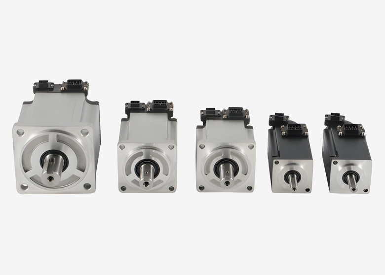
Motion control motors for laser marking and engraving equipment perform several different jobs. They may position a workpiece beneath a scan head, move a gantry, adjust the focus height, or rotate a cylindrical part.
The correct motor depends on which component moves and how that movement interacts with the laser. A motor suitable for indexing a fixture may not suit continuous rotary engraving or rapid gantry reversals.
Start by defining the motion architecture, then evaluate load, torque, speed, feedback, and controller compatibility. This approach provides a more useful specification than selecting a motor by power or encoder resolution alone.
Table of Contents
Toggle
Where Motors Are Used in Laser Marking and Engraving Equipment
Galvanometer scanning and mechanical positioning
A galvanometer scanner steers the beam using small mirrors and specialized actuators. In many marking machines, the workpiece and scan head remain stationary while the mirrors trace the marking pattern within the optical field.
A conventional industrial servo motor is not a direct replacement for a galvanometer actuator.
Mechanical axes extend the machine’s capability. They can move larger parts, present multiple marking locations, adjust height, or rotate a workpiece. Some systems coordinate these axes with the scanner during processing.
Motion function
What moves
Main selection concerns
X/Y positioning stage
Workpiece or fixture
Travel, payload, repeatability, and settling time
Gantry engraving
Laser head or bridge assembly
Torque-speed performance, moving mass, stiffness, and reversal behavior
Z-axis adjustment
Head, lens assembly, or workpiece platform
Vertical load, focus-position repeatability, and load-holding arrangements
Rotary axis
Chuck, roller, fixture, and workpiece
Inertia, runout, slip, angular positioning, and synchronization
Coordinated stage and scanner
Mechanical axis and beam position
Timing, calibration, coordinate alignment, and controller functions
Motion quality is only part of marking quality
Positioning errors and vibration can distort text, shift repeated passes, or create visible seams. However, marking quality also depends on laser power, pulse settings, focus, optics, material, and fixturing.
A blurred mark does not automatically indicate a motor problem. Likewise, a high-resolution encoder cannot guarantee readable codes or consistent engraving depth.
Define the required result at the workpiece: dimensional accuracy, placement tolerance, depth variation, code readability, or an agreed visual standard.
How to Select Motion Control Motors for Laser Marking
Compare motor types against the duty
Open-loop stepper systems can be suitable when their available torque, speed, and positioning performance meet the requirement. They can lose position if the load exceeds their operating capability, without detecting the missed movement.
Closed-loop steppers add feedback, while servo systems use feedback to regulate motion within their operating limits. Neither eliminates every mechanical or control error.
Rotary servos driving screws, belts, or gears are options for mechanical axes. Linear motors provide direct linear force and remove that rotary-to-linear transmission, but still require suitable guides, feedback, thermal design, and control.
Tiger Motion’s standard servo motors provide a starting point for rotary-axis evaluation. Its linear motor range can also be reviewed where direct linear motion suits the machine design.
Size for torque, speed, and operating cycle
For rotary motors, calculate acceleration torque, friction, external loads, and the inertia reflected through the transmission. For a linear motor, calculate the corresponding force and speed requirements.
Check peak demand and continuous thermal duty separately. Include the complete production cycle, with indexing, marking, reversals, holding, and dwell periods.
Important inputs include:
Moving mass or rotary inertia.
Transmission ratio, screw lead, or pulley geometry.
Maximum velocity and required acceleration.
RMS and peak torque, or continuous and peak force.
Drive current and overload limits.
Deceleration energy.
Ambient temperature and mounting conditions.
For a vertical axis, also assess gravity loading and the required holding or counterbalance arrangement. Confirm whether a motor brake is intended for holding only; do not assume it is suitable for routine dynamic stopping.
Deep engraving does not inherently require high motor torque because the laser removes the material. Motor demand comes from moving and holding the axis, while repeated passes increase the importance of registration and thermal stability.
Evaluate settling time and smoothness
For an indexed marking station, the important interval is often the time required to move and settle within the permitted position band.
Higher acceleration may shorten travel but excite vibration, increasing settling time. Evaluate the complete move-and-settle cycle.
For gantry raster engraving, check repeated reversals, structural resonance, and the motion controller’s acceleration and jerk settings. Jerk describes the rate of change of acceleration. Suitable motion profiles can reduce mechanical excitation, although they may also affect cycle time.
Separate feedback resolution from accuracy
Encoder resolution describes the number of distinguishable position values. For example:
Single-turn resolution
Position values per revolution
17-bit
131,072
20-bit
1,048,576
23-bit
8,388,608
These values are not guarantees of motor-shaft accuracy or workpiece positioning accuracy. Transmission error, backlash, compliance, runout, alignment, and temperature also matter.
Absolute feedback can reduce referencing requirements in an appropriately designed system. However, single-turn and multi-turn behavior differ. Machine referencing, position retention, and recovery after maintenance must still be defined. Absolute feedback does not replace travel limits or machine safety functions.
Rotary Engraving and Scanner Coordination
Rotary axes for cylindrical parts
A rotary axis may index a part between marking operations or rotate continuously during processing. These modes require different controller functions.
For a chuck system, evaluate workpiece inertia, clamping, balance, runout, and gearbox behavior. For a roller system, also consider contact conditions and possible slip.
For continuous engraving, the controller must coordinate angular motion with the marking pattern and laser timing. Diameter data and geometry are important when converting an unwrapped design into surface coordinates.
A servo can improve motion regulation in a suitable system, but it cannot eliminate a seam caused by incorrect diameter settings, workpiece slip, or optical calibration.
Indexed fields versus coordinated motion
Large-area marking can use separate positioning and scanning steps. The stage moves to a location, settles, and the scanner marks a field.
Another approach coordinates mechanical movement and scanner motion during processing. This requires suitable control hardware, timing, coordinate transformations, and calibration.
Marking on the fly commonly uses motion information, such as conveyor encoder feedback, to compensate for a moving workpiece. It is not automatically the same function as coordinated large-area stage-and-scanner processing.
Features such as Infinite Field of View are controller-specific capabilities. They should not be assumed to be available simply because servo motors are installed.
Z-axis focus adjustment
A Z axis may set focus between jobs, reposition between engraving layers, or participate in a coordinated process.
Some three-dimensional scanning systems instead use dynamic focusing optics. The required solution depends on the optical architecture, surface geometry, and process speed.
Specify the required focus range, positioning behavior, and coordination method before selecting the motor.
Controller Integration and Production Validation
Verify the full hardware chain
Software names alone do not establish compatibility. EZCAD2, EZCAD3, LightBurn, and OEM software operate with particular controllers and supported hardware configurations.
Confirm:
Controller model and software version.
Supported external-axis functions.
Command interface and electrical requirements.
Compatible motor, encoder, and drive.
Homing, limits, alarms, and enable signals.
Scanner interface and laser timing functions.
Rotary, indexing, or coordinated-motion support.
Pulse/direction is a digital command interface. EtherCAT can support synchronized motion and diagnostics, but it is not immune to electromagnetic interference. Available torque and temperature information depends on the drive and its supported data.
Hatch spacing and pass count are process settings. They must be coordinated with scan speed and laser parameters; they are not substitutes for correct axis scaling or trajectory timing.
Commission mechanics and controls together
Before tuning, inspect guides, couplings, bearings, screw or belt drives, and fixture rigidity. Confirm alignment, travel direction, command scaling, and limits.
Use the drive manufacturer’s commissioning procedure. Automatic tuning may provide a starting point, but it does not remove the need to test the actual machine.
Follow model-specific instructions for shielding, grounding, cable routing, and environmental protection. Select ingress protection for the real exposure and installation. No single IP rating is mandatory for every enclosed laser machine.
Validate marks and business results
Test representative parts, fixtures, and production settings. Depending on the application, check:
Placement and dimensions at multiple stage positions.
Registration between repeated engraving passes.
Rotary seam alignment and workpiece slip.
Settling time before marking begins.
Code readability using the agreed verification method.
Cycle time and thermal drift during extended operation.
Measure whether the upgrade reduces the actual bottleneck. Laser processing time, handling, focusing, and inspection may dominate the cycle. Use measured cycle time, scrap, energy, and maintenance data when estimating return on investment.
For unusual mounting or feedback requirements, discuss custom servo motor options with Tiger Motion. Confirm the proposed configuration and integration responsibilities before ordering.
Frequently Asked Questions
1. Does every laser marking machine need a servo motor?
No. A galvo-only marking system may not need external positioning axes. Where mechanical axes are used, select steppers, servos, or other actuators according to the load and performance requirement.
2. Can a standard servo motor replace a galvanometer motor?
Not as a direct substitution. Galvanometer scanners use specialized actuators, feedback, optics, and control electronics. Standard industrial servos generally serve the machine’s mechanical positioning axes.
3. Does a MOPA or UV laser require servo-driven axes?
The laser-source type alone does not determine the motor. Define the required mechanical movement, placement tolerance, cycle time, and control architecture.
4. What encoder resolution is needed for engraving?
There is no universal bit-depth requirement. Evaluate feedback resolution and accuracy alongside transmission geometry, mechanical errors, and workpiece-level tolerances.
5. Can a servo-driven rotary axis eliminate engraving seams?
It can support controlled rotation, but seam quality also depends on diameter settings, clamping or roller slip, runout, calibration, and laser synchronization. Validate the complete process on representative parts.
Discuss Your Marking and Engraving Axis Requirements
Share your axis function, travel, payload or rotary inertia, transmission details, motion targets, supply voltage, and controller model with Tiger Motion.
Contact Tiger Motion to discuss motor options and request model-specific information. State whether the axis indexes between marks or moves during processing so the requirements can be reviewed accurately.