Selecting servo motors for laser cutting machines starts with the motion requirements of each axis. Moving mass, acceleration, transmission ratio, duty cycle, and controller compatibility all matter. Motor wattage alone cannot establish cutting speed or positioning accuracy.
For machine builders and retrofit buyers, the aim is to select a motor and compatible drive that can follow the required trajectory within defined error limits. The mechanical system, CNC controller, and laser process must support the same performance target.
This guide focuses on X/Y axis motion control, including motor sizing, feedback, dual-drive gantry synchronization, and commissioning.
Table of Contents
Toggle
How Servo Motors Support X/Y Axis Motion Control
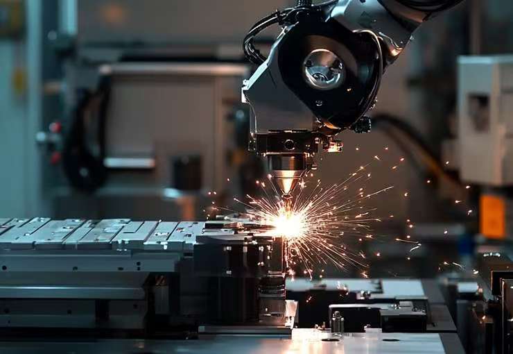
A laser cutting machine coordinates axis movement with laser output to follow a programmed path. Motion errors can affect part geometry, while vibration and inappropriate speed changes may affect the cut.
However, edge quality also depends on focus, laser power, assist gas, material, and process settings. A servo upgrade cannot correct every cutting defect.
Understand the load on each axis
In a common moving-gantry arrangement, one axis moves the cutting-head carriage along the bridge. The other moves the bridge assembly, including the carriage and associated equipment.
Axis names vary between machine designs. Confirm the actual layout rather than assuming that X always carries the lighter load.
Motion requirement
Head-carriage axis
Bridge-travel axis
Moving load
Cutting head, carriage, and attached components
Bridge, carriage, and other moving equipment
Important sizing inputs
Cable drag, friction, acceleration, and transmission
Total moving mass, transmission, and drive arrangement
Mechanical concerns
Carriage stiffness, belt compliance, and reversal behavior
Bridge stiffness, alignment, and possible racking
Control concerns
Tracking during short moves and direction changes
Tracking and synchronization where two drives are used
Include cable carriers, hoses, fittings, and moving motor or gearbox assemblies in the load assessment.
What closed-loop feedback does
A servo system uses feedback to regulate motion. Depending on the architecture, position, velocity, and current control functions are shared between the controller and drive.
Feedback helps the system detect and correct deviations. It does not guarantee zero following error during acceleration or cutting. Define acceptable tracking and contour errors, then verify them under representative operating conditions.
Motor-mounted feedback measures the motor shaft. Backlash, belt stretch, and structural deflection downstream of that encoder may still affect the cutting head’s position.
Open-loop steppers can lose position if overloaded without detecting the error. Closed-loop steppers and servos provide different feedback and operating characteristics; compare their actual torque-speed performance against the application.
How to Size Servo Motors for Laser Cutting Machines
Start with the required motion profile and mechanical transmission. Calculate each axis separately before selecting a motor-drive combination.
Check peak torque, continuous duty, and speed
The motor must provide enough torque to accelerate the load and overcome resistance. It must also remain within its thermal limits throughout the operating cycle.
Check:
Peak torque during acceleration and deceleration.
RMS torque over the representative duty cycle.
Required motor speed at maximum axis velocity.
Available torque at that speed.
Drive current capacity and overload duration.
Deceleration energy and regenerative handling.
Ambient temperature and mounting conditions.
RMS torque is useful for thermal assessment, but prolonged overloads also require checking the motor and drive’s permitted operating limits.
The rated-power relationship is:
Torque (N·m) = 9550 × Power (kW) ÷ Speed (rpm)
For example, at a rated speed of 3,000 rpm, 400 W corresponds to approximately 1.27 N·m, while 750 W corresponds to approximately 2.39 N·m. These are calculation examples, not specifications for every motor in those power classes.
They do not establish fixed linear speeds such as 300 or 600 mm/s. Linear speed depends on screw lead, pulley or pinion geometry, transmission ratio, and motor speed. Cutting speed also depends on the laser process.
Evaluate reflected inertia
Inertia matching compares the load inertia reflected to the motor shaft with the motor’s rotor inertia. It is not a direct comparison between gantry mass and motor mass.
For a rotary load behind a reduction gearbox, reflected load inertia decreases with the square of the reduction ratio. Translating loads require calculations based on the screw, pulley, or rack-and-pinion arrangement.
There is no universal requirement to keep every laser axis below a 5:1 ratio. The acceptable ratio depends on the drive, mechanical stiffness, response target, and tuning capability.
A lower-inertia motor may reduce the torque needed to accelerate its own rotor. A higher-inertia motor may suit some loads, but it also increases acceleration demand. Neither option is automatically better.
Select the transmission with the motor
A gearbox can reduce motor-side load inertia and increase output torque, while introducing backlash, compliance, losses, and additional components.
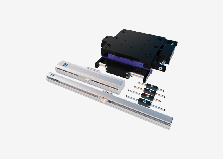
Belt drives, ball screws, rack-and-pinion systems, and linear motors have different trade-offs. Direct coupling can be suitable when torque, speed, stiffness, and inertia requirements are satisfied.
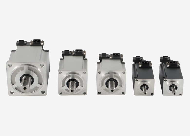
Review Tiger Motion’s standard servo motors against the calculated requirements. Confirm the selected model’s torque-speed curve, rotor inertia, feedback configuration, and compatible drive before finalizing the design.
Encoder Feedback, Controller Compatibility, and Gantry Synchronization
A suitable motor still needs a compatible drive and motion controller. Confirm the complete control architecture before purchasing hardware.
Encoder resolution is not machine accuracy
Encoder resolution describes how finely angular position is represented. For example, a 17-bit single-turn position value has 131,072 distinguishable positions per revolution; a 23-bit value has 8,388,608.
These figures do not establish encoder accuracy or cutting-head positioning accuracy.
Machine performance also depends on transmission errors, backlash, structural deflection, alignment, temperature, and control behavior. Distinguish between encoder resolution, positioning accuracy, repeatability, and dynamic contour accuracy.
For motor-drive matching, verify the encoder interface and configuration. A high-resolution encoder is useful only when the drive supports it and the mechanical system benefits from it.
Match the interface to the controller
Pulse/direction and industrial motion networks are possible command interfaces. Pulse/direction is digital; it should not be described as an analog connection.
Interface consideration
What to verify
Pulse/direction
Electrical levels, signal type, maximum pulse frequency, and command scaling
EtherCAT
Controller support, drive compatibility, operating modes, cycle time, and synchronization configuration
Other interfaces
Supported command modes, diagnostics, update behavior, and application suitability
Feedback
Whether feedback closes locally in the drive or is also used by the controller
Machine integration
Enable, alarm, homing, limits, and coordinated stopping behavior
EtherCAT can support synchronized multi-axis motion, but it does not automatically eliminate contour errors or guarantee compatibility.
CypCut, Ruida-based systems, and LinuxCNC cover different hardware and software configurations. Verify the exact controller model and documentation rather than relying on the software name alone. A retrofit does not inherently require custom FPGA programming.
Dual-drive gantries need coordinated control
Some wide gantries use two motors to drive opposite sides of the bridge. This arrangement requires controlled synchronization to limit skew and mechanical stress.
Check gantry homing and squaring, position-difference monitoring, fault handling, and the stopping response if one drive fails.
Two motors receiving the same command do not, by themselves, guarantee that the bridge remains square. Mechanical alignment and the controller’s gantry functions must work together.
Integration, Tuning, and Performance Validation
Replacing a stepper with a servo involves more than matching flange dimensions. Check shaft geometry, mounting, coupling capacity, supply requirements, feedback cables, and controller interfaces.
A complete power-supply replacement or gearbox installation may be necessary in some retrofits, but neither should be assumed before evaluation.
Check the mechanics before raising gains
Inspect guide alignment, rack engagement, belt tension, bearings, couplings, and structural stiffness. Mechanical play or binding can produce symptoms that resemble control problems.
Use manufacturer-supported tuning procedures. Automatic tuning may provide a starting point; further adjustment depends on the application.
Excessive gain can excite resonance. Filters and feedforward functions may help, but they cannot repair worn components or an inadequately stiff structure. Also, not every drive exposes a conventional PID structure for manual adjustment.
Follow the equipment manufacturers’ instructions for grounding, shielding, cable routing, and termination. Do not apply a universal rule that every encoder shield must be grounded at only one end.
Validate performance with representative paths
Begin commissioning with the laser disabled and conservative motion settings. Verify direction, scaling, limits, homing, and fault responses before increasing performance.
Then test:
Long moves for speed and thermal behavior.
Short repeated moves for acceleration and settling.
Circles and diagonal paths for coordinated motion.
Direction reversals for backlash or compliance effects.
Full-travel movement for cable drag and alignment.
Gantry squaring and synchronization where applicable.
Finally, evaluate representative cutting jobs using defined material and process settings. Record dimensional results, contour quality, cycle time, and alarms.
Measure actual production gains. A servo upgrade does not support a universal promise of a 40% speed increase or a fixed payback period.
Frequently Asked Questions
1. What size servo motor does a laser cutting machine need?
There is no universal size. Calculate moving load, transmission, acceleration, speed, friction, and duty cycle for each axis. A machine designation such as “1390” does not provide enough information to select a motor.
2. Is a 750 W servo always better than a 400 W servo?
No. Compare torque-speed curves, rotor inertia, dimensions, drive requirements, and thermal duty. More rated power does not automatically improve contour accuracy or shorten the cutting cycle.
3. Do all laser cutting machines need EtherCAT?
No. The interface must suit the controller architecture and performance requirements. EtherCAT can support synchronized motion, while other compatible interfaces may also meet the machine’s needs.
4. Does a high-resolution encoder eliminate positioning errors?
No. It provides finer position information, but mechanical and control errors remain possible. Verify positioning and contour performance at the machine level.
5. Why does a laser cutting machine vibrate after a servo retrofit?
Possible causes include excessive control gain, mechanical resonance, loose components, misalignment, transmission compliance, or unsuitable motion settings. Inspect the mechanics and review drive diagnostics before changing tuning parameters.
Discuss Your X/Y Axis Servo Requirements
Selecting motors for a new laser cutter or evaluating a retrofit? Share your axis layout, moving masses, transmission details, speed and acceleration targets, duty cycle, supply voltage, and controller model with Tiger Motion.
Contact Tiger Motion to discuss motor options and request model-specific technical information. Include encoder, shaft, flange, and cable requirements so compatibility can be reviewed before quotation.