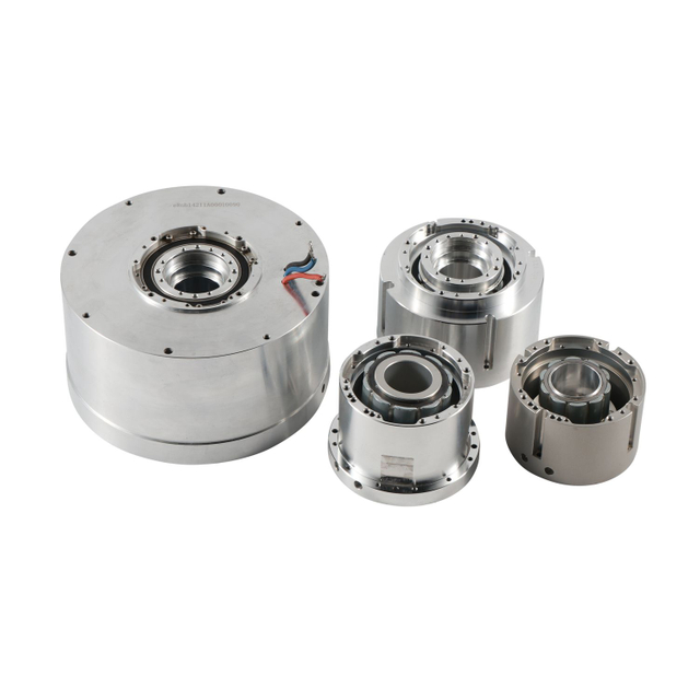
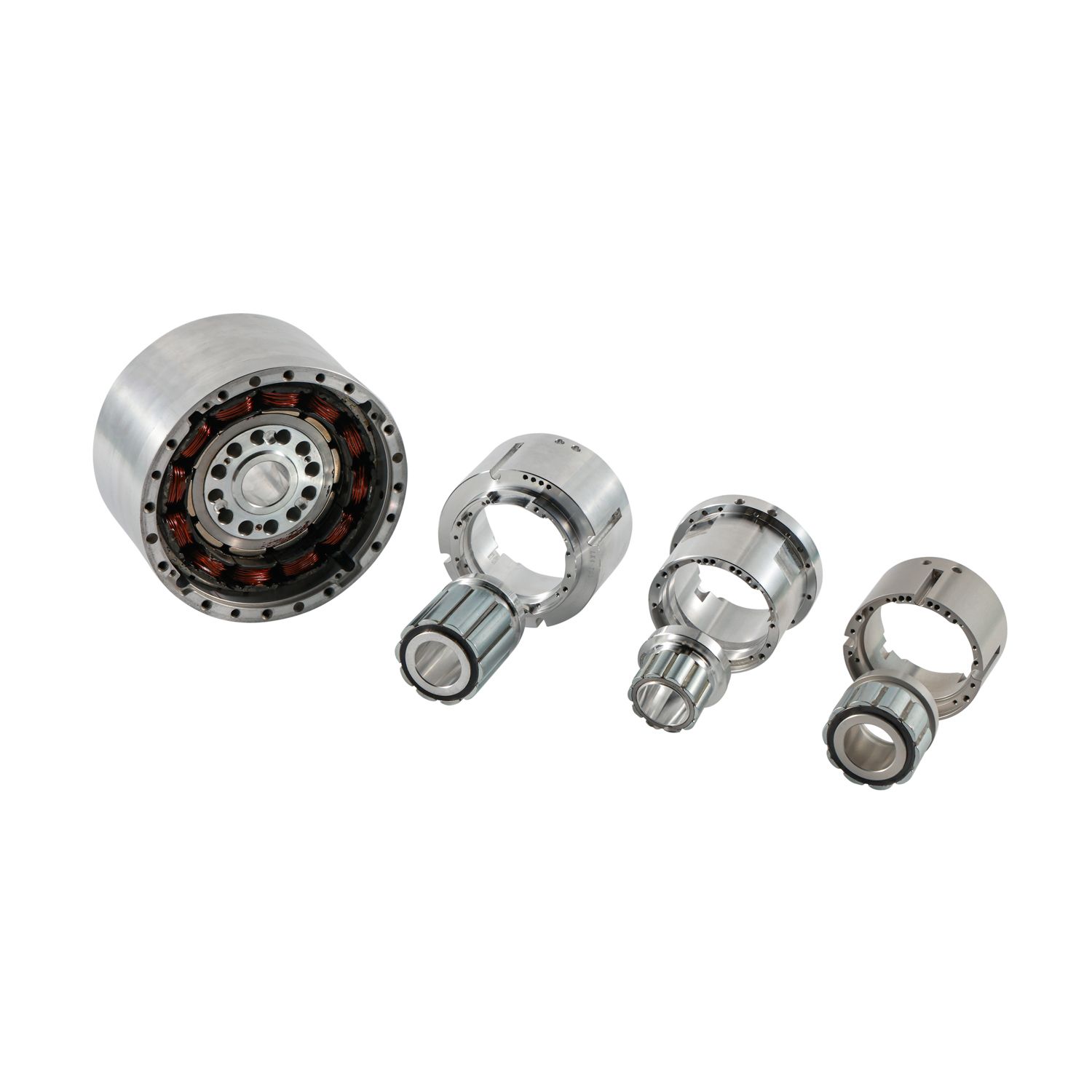
In advanced robotics and precision automation, the physical constraints of traditional powertrain components increasingly bottleneck system performance and design miniaturization. Standard housed motors paired with mechanical transmissions introduce backlash, increase footprint, add weight, and complicate the routing of essential system utilities. Power lines, data cables, fluids, and optics must often route awkwardly around bulky gearboxes and motor housings, creating failure points and limiting range of motion. Hollow Frameless Motors provide a direct-drive alternative that eliminates mechanical compliance and integrates directly into the machine structure. This guide evaluates the technical advantages and integration trade-offs of specifying frameless architectures for high-performance applications. We will examine spatial efficiency, utility routing, dynamic performance, and the mechanical design capabilities required to manage tight tolerances, maintain the rotor-stator air gap, and engineer custom thermal management solutions for your next machine build.
Optimized Spatial Efficiency: By eliminating endbells, bearings, and external housings, frameless motors reduce overall mass and footprint, allowing for highly compact joint designs.
Simplified Utility Routing: The large inner diameter (hollow bore) permits the unobstructed passage of cables, laser beams, or fluid lines directly through the axis of rotation, reducing external cable wear and snag hazards.
Superior Dynamic Performance: Direct coupling to the load eliminates gearbox backlash and mechanical elasticity, resulting in higher servo stiffness, faster settling times, and superior positional accuracy.
Integration Complexity: Realizing these advantages requires rigorous in-house mechanical design capabilities to manage tight tolerances, maintain the rotor-stator air gap, design specialized assembly tooling, and engineer custom thermal management solutions.
What Is a Hollow Frameless Motor and How Does It Work?
A frameless motor represents the purest form of electromagnetic power generation. It strips away all external packaging. You receive only the essential active components required to generate torque. This two-part construction consists solely of a separate magnetic rotor and a wound stator. The factory does not install bearings, shafts, or feedback devices. The machine builder must integrate these elements into the final assembly. You take on the responsibility of aligning the components and supporting the rotating mass.
Rotors typically feature high-energy neodymium-iron-boron (NdFeB) permanent magnets. Stator designs vary based on performance requirements. You must choose between concentrated and distributed stator windings. Concentrated windings offer shorter end turns and higher slot fill factors. Distributed windings provide smoother back-EMF waveforms. Rotor configurations also differ. Surface permanent magnet (SPM) designs mount magnets on the rotor exterior. Interior permanent magnet (IPM) designs embed magnets within the rotor lamination stack, offering higher structural integrity for high-speed operation.
The stator consists of stacked steel laminations. These laminations reduce eddy current losses. Copper wire is wound through the slots in the lamination stack. The winding pattern determines the motor's electrical characteristics. Engineers encapsulate the windings in a high-temperature resin. This potting process improves thermal conductivity and protects the wires from environmental damage. The rotor consists of a steel hub with permanent magnets bonded to its surface or embedded within. A retaining sleeve often wraps around surface-mounted magnets. This sleeve prevents the magnets from detaching at high rotational speeds.
The direct drive principle defines how these motors operate. The rotor connects directly to the driven load. No intermediate mechanical transmission exists. You eliminate belts, pulleys, and gearboxes. This establishes a high-performance baseline for motion control. Specifying this technology requires meeting specific success criteria. You should consider frameless designs when your application demands high torque density at low speeds. Extreme precision requirements and severe spatial constraints also justify the integration effort.
Key Benefits of Hollow Frameless Motors
The Hollow Bore Advantage: Centralized Utility Routing
The defining feature of these motors is the large inner diameter. This hollow bore enables centralized utility routing. Cable management becomes significantly easier in multi-axis systems like robotic arms. Routing power, encoder cables, and pneumatic lines through the center bore prevents cable fatigue. It eliminates twisting and external snagging hazards. Your machine maintains a clean exterior profile.
Consider a six-axis robotic arm. Traditional designs route cables along the outside of the arm. These cables bend and flex with every movement. Over time, the internal wires break. A hollow bore allows you to route the cables internally, directly through the center of each joint. The cables experience minimal flexing. This drastically improves the mean time between failures for the wiring harness. You spend less time replacing damaged cables and more time running production.
Many advanced applications require unobstructed central axes. LiDAR systems pass laser beams directly through the motor center. Laser processing heads route optics through the bore. Medical imaging and chemical processing equipment pass fluid lines through the rotation axis. The hollow design accommodates these requirements perfectly. It also simplifies slip ring integration. You can easily mount through-bore slip rings inside the rotor. This allows for continuous 360-degree rotation without cable binding or twisting.
Superior Form Factor and Mass Reduction
Frameless motors optimize weight by utilizing the machine's existing structure. The machine frame acts as the motor housing. You eliminate redundant mechanical casings, endbells, and heavy output shafts. This mass reduction is critical for mobile and robotic applications. Lowering the distal weight in robotic linkages improves the center of gravity. Reduced inertia means you need less torque to accelerate and decelerate the system.
Engineers gain immense flexibility in specifying custom form factors. You can select pancake profiles featuring large diameters and short axial lengths. These flat designs fit into tight spatial envelopes where traditional cylindrical motors fail. The form factor adapts to the machine, rather than forcing the machine to adapt to the motor. For example, in a pan-tilt gimbal mechanism, a pancake motor allows you to keep the optical payload close to the axis of rotation. This minimizes the swept volume of the gimbal and reduces the torque required to stabilize the camera.
High Servo Stiffness and Zero Backlash
Removing mechanical compliance transforms system performance. Gearboxes, belts, and couplings introduce torsional hysteresis. They flex under load. Direct drive eliminates these compliant elements. The load couples rigidly to the rotor. This results in exceptional servo stiffness. The control loop can operate at much higher gains without instability.
Dynamic response improves dramatically. You achieve higher bandwidth, faster settling times, and superior tracking accuracy. The system responds instantly to command changes. Modern frameless designs also optimize slot and pole configurations. They use skewed laminations to minimize torque ripple and cogging. This ensures ultra-smooth operation at very low speeds. Furthermore, eliminating gear meshing reduces audible noise and mechanical vibration. In precision machining applications, this lack of vibration translates directly to superior surface finishes on the manufactured parts.
Hollow Frameless Motor vs Housed Motor: Key Differences
Performance Metrics Comparison
Evaluating performance requires looking at torque density and speed characteristics. Frameless motors deliver exceptional continuous and peak torque relative to their active electromagnetic volume. They excel in low-speed, high-torque regimes. Housed motors typically require gear reduction to achieve similar torque at low speeds. The direct connection means you do not lose power through mechanical inefficiencies.
System time constants also differ. The electrical time constant and mechanical time constant dictate how fast the motor responds. Frameless direct-drive designs often exhibit superior mechanical time constants compared to housed gearmotors. Efficiency improves because you eliminate transmission friction and viscous damping losses inherent in gearboxes. You convert more electrical power directly into useful mechanical work.
Metric
Hollow Frameless Motor (Direct Drive)
Housed Motor with Gearbox
Torque Delivery
Direct to load, high torque at low speeds.
Requires mechanical reduction for high torque.
Backlash
Zero.
Present (varies by gear type).
Utility Routing
Internal through hollow bore.
External routing required.
Mechanical Efficiency
High (no transmission losses).
Lower (friction and damping losses).
Integration Effort
High (requires custom housing/bearings).
Low (plug-and-play).
Servo Stiffness
Extremely high due to direct coupling.
Limited by gearbox compliance.
Motor Sizing and Selection Methodology
Sizing a frameless motor requires careful duty cycle analysis. You cannot rely on arbitrary horsepower metrics. Calculate the thermal-equivalent RMS torque over the complete motion profile. This ensures the motor will not overheat during continuous operation. Peak torque requirements dictate the maximum current the drive must supply during acceleration.
Sizing a direct-drive motor involves several critical steps:
Define the motion profile: Map out the required acceleration, constant velocity, and deceleration phases.
Calculate load inertia: Determine the exact moment of inertia for all moving parts attached to the rotor.
Determine peak torque: Calculate the torque required to accelerate the load inertia at the desired rate.
Calculate RMS torque: Determine the root-mean-square torque over the entire duty cycle to evaluate thermal requirements.
Select the motor: Choose a motor with a continuous torque rating higher than the calculated RMS torque and a peak torque rating higher than the calculated peak torque.
Direct-drive applications change the rules for inertia matching. Geared systems traditionally require a 1:1 load-to-rotor inertia ratio for stability. Direct coupling bypasses this limitation. You can operate successfully with load-to-rotor inertia ratios of 100:1 or higher. The stiff mechanical connection and advanced control algorithms make this possible. This allows you to drive massive loads with relatively small motors, provided the motor can generate sufficient torque.
Common Hollow Frameless Motor Integration Risks and Solutions
Mechanical Integration and Tolerance Stacking
Frameless integration demands rigorous mechanical design. Maintaining the precise concentricity and air gap between the unhoused rotor and stator is a critical engineering challenge. This air gap often measures down to tenths of a millimeter. Tolerance stacking in your machined parts can easily consume this gap, leading to catastrophic rotor-stator contact. You must machine the stator housing and the rotor shaft to exacting tolerances. Runout must be kept to an absolute minimum.
Magnetic attraction forces present significant assembly hazards. The radial magnetic pull between the rotor and stator is immense. You must use non-magnetic assembly fixtures and guides. Attempting assembly without proper tooling risks component damage and severe operator injury. We typically design custom insertion tools using aluminum or 300-series stainless steel. These tools guide the rotor into the stator while resisting the radial pull.
Bearing selection also shifts to the system designer. You must specify bearings that handle the payload while resisting magnetic radial forces. They must maintain rigid axial and radial runout profiles under all operating conditions. Cross-roller bearings are a popular choice for frameless motor joints. They handle radial, axial, and moment loads simultaneously within a very compact axial footprint.
Feedback Device (Encoder) Mounting
Direct drive requires high-resolution feedback. Mounting optical or magnetic ring encoders directly to the hollow shaft introduces alignment complexities. The encoder readhead must maintain precise distance and orientation relative to the scale. Any runout in the shaft directly degrades positional accuracy. You must machine the encoder mounting surfaces with the same precision as the bearing journals.
Commutation alignment, or phasing, adds another step. You must determine the exact offset angle between the encoder zero position and the rotor's magnetic poles. The servo drive needs this information for proper sinusoidal commutation. Incorrect phasing leads to inefficient operation or failure to rotate. Many modern drives use wake-and-shake algorithms to determine this offset automatically at power-up. Alternatively, you can use Hall effect sensors for initial commutation before switching to the high-resolution encoder.
Thermal Mitigation Strategies
Thermal management responsibility shifts entirely to the system integrator. The machine frame acts as the primary heatsink. You must design adequate thermal paths to dissipate heat generated by the stator windings. Poor heat dissipation leads to elevated winding temperatures. You must ensure a tight interference fit or use thermally conductive epoxies between the stator and the housing to minimize thermal resistance.
Excessive heat poses a severe demagnetization risk. High temperatures can irreversibly demagnetize the NdFeB rotor magnets. You must embed temperature sensors, such as PTC thermistors, NTC thermistors, or RTDs, directly into the stator windings. These sensors allow the drive to monitor temperature and prevent damage. Cooling methods vary based on duty cycle. Passive conduction through the machine frame works for many applications. High continuous torque applications may require active cooling, such as custom liquid jackets or forced air circulation. When designing a liquid cooling jacket, you must ensure a tight interference fit between the stator and the cooling sleeve to maximize heat transfer.
Best Applications for Hollow Frameless Motors
Surgical Robotics and Medical Devices
Medical equipment relies heavily on frameless technology. MRI machines, CT scanners, and surgical robot joints utilize these motors. Non-magnetic variations exist for sensitive imaging environments. The hollow bore allows imaging components and cables to pass through the rotation axis. Smooth, cog-free motion enables the precise manipulation required in surgical procedures. In a surgical robot, the surgeon relies on haptic feedback. Any friction or backlash in the joints distorts this feedback. Direct-drive frameless motors provide the transparency required for accurate haptic rendering.
Aerospace and Defense Systems
Aerospace applications demand extreme optimization. Gimbal systems, targeting pods, and satellite communication antennas use frameless motors. The primary value driver is SWaP-C (Size, Weight, Power, and Cost) optimization. These direct-drive systems provide exceptional reliability in harsh, high-vibration environments where gearboxes would fail. In a satellite antenna pointing mechanism, the motor must operate in a vacuum. This eliminates convective cooling. The system must rely entirely on conductive heat transfer through the gimbal structure.
Industrial Automation and Cobots
Modern factory automation depends on compact power. Collaborative robot (cobot) joints, rotary indexing tables, and semiconductor manufacturing equipment leverage frameless designs. They offer high torque density in a compact joint package. Direct drive enables safe, predictable force feedback, known as proprioception. This allows cobots to sense collisions and operate safely alongside human workers. In semiconductor wafer handling, the motors must operate in cleanrooms. Frameless motors eliminate the particulate generation associated with wearing gear teeth and degrading lubricants.
Conclusion
A Hollow Frameless Motor is an ideal solution for machines requiring compact integration, zero backlash, high servo stiffness, precise positioning, and centralized utility routing. However, successful implementation depends on accurate motor sizing, strict rotor-stator alignment, appropriate bearing and encoder selection, specialized assembly tooling, and effective thermal management.
Shenzhen Tiger Motion Control Technology provides motion control solutions for advanced automation and precision equipment applications. Its technical support helps machine builders address motor selection, mechanical integration, control performance, and system reliability requirements.
Initiate a comprehensive design review with a motion control engineer to assess application feasibility.
Request 3D CAD models from the manufacturer to verify spatial envelopes and integration points.
Design and fabricate specialized, non-magnetic assembly tooling before ordering production units.
Order a prototype evaluation kit to validate thermal performance and control loop stiffness.
FAQ
Q: What is the difference between a frameless motor and a housed motor?
A: A frameless motor is supplied as separate rotor and stator components without bearings, endbells, or a shaft. The machine builder integrates these active electromagnetic parts directly into their own mechanical structure. A housed motor is a complete, factory-assembled unit ready to bolt onto a machine.
Q: How do you mount a hollow frameless motor?
A: You typically press-fit, bond with structural adhesives, or mechanically clamp the stator into the machine frame. The rotor is secured to the driven shaft using adhesives, shrink fits, or mechanical clamping rings, ensuring precise concentricity.
Q: What are the assembly hazards associated with hollow frameless motors?
A: The permanent magnets generate extreme radial pull forces. If the rotor is inserted off-center, it will violently snap against the stator, crushing fingers and shattering magnets. You must use specialized, non-magnetic alignment fixtures during assembly.
Q: Do hollow frameless motors require gearboxes?
A: No, they are designed for direct-drive configurations, coupling directly to the load to eliminate backlash. However, in applications requiring extreme torque multiplication in a small space, they can be paired with hollow-shaft strain wave gears.
Q: How is heat managed in a frameless motor?
A: Heat dissipates through conduction from the stator into the host machine's structure. For high-power applications, integrators machine custom liquid cooling channels into the surrounding housing. Embedded thermal sensors monitor winding temperatures to prevent magnet demagnetization.
Q: What type of encoder is best for a hollow frameless motor?
A: Large-diameter optical or magnetic ring encoders are ideal. They match the motor's hollow bore profile, allowing cables and utilities to pass completely through the center of both the motor and the feedback device.